Random number generation circuit
a technology of random number generation and oscillation circuit, which is applied in the direction of pulse generator, pulse technique, instruments, etc., can solve the problems of inability to reduce the probability of collision of finally obtained random numbers, unstable oscillation circuit composed of cmos inverters, and difficulty in conventional methods to reduce the probability of collision of random numbers
- Summary
- Abstract
- Description
- Claims
- Application Information
AI Technical Summary
Benefits of technology
Problems solved by technology
Method used
Image

Examples
first embodiment
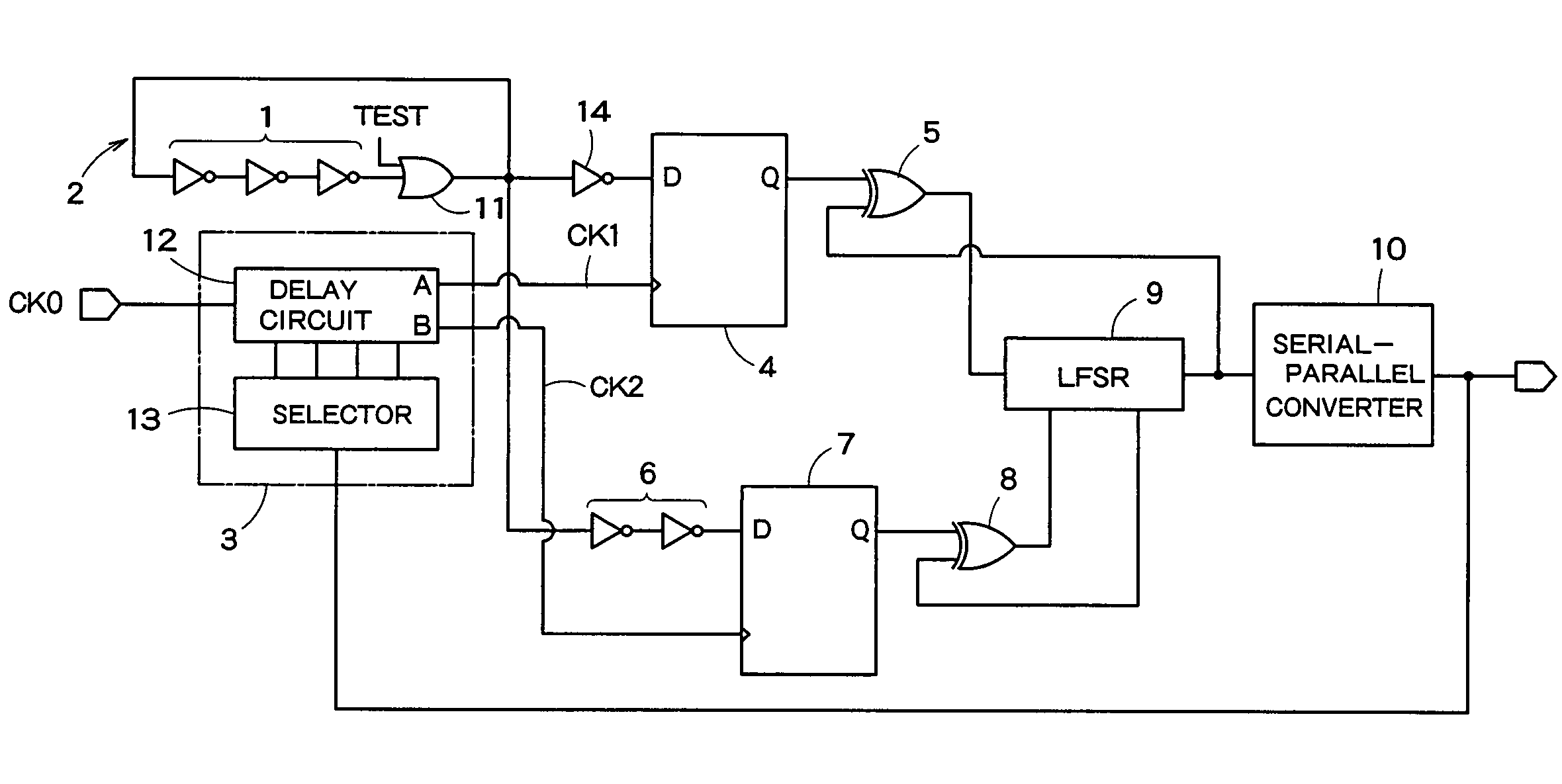
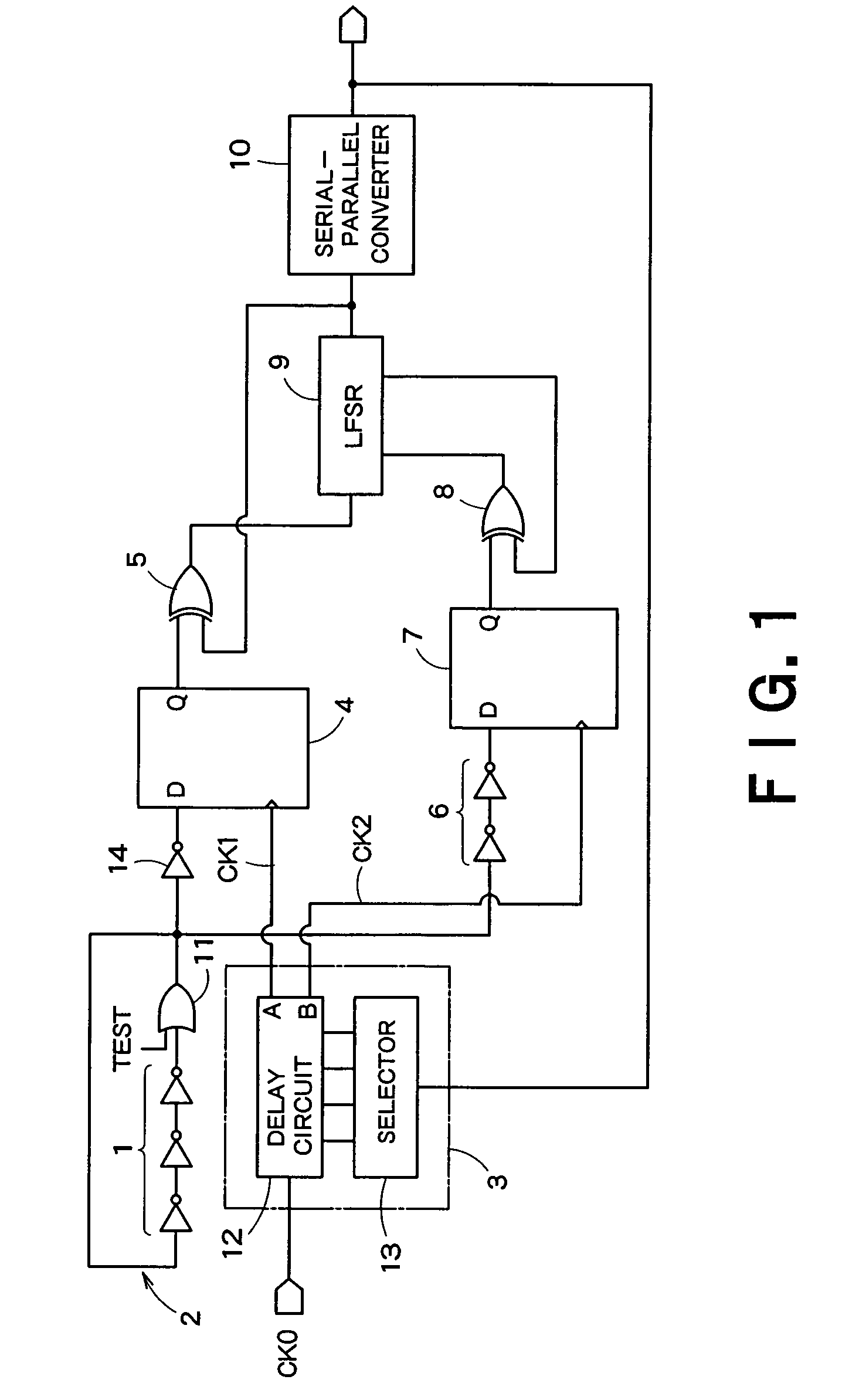
[0038]FIG. 1 is a block diagram showing a schematic configuration of a random number generation circuit according to an embodiment of the present invention. The random number generation circuit in FIG. 1 is provided with a ring oscillator 2 which has an odd number of cascaded inverters 1, a delay control circuit 3 which delays a reference clock signal CK0 to generate delay reference clock signals CK1, CK2, a first flip-flop 4 which latches the oscillation signal generated by the ring oscillator 2 with the delay reference clock signal CK1, a first EXOR circuit 5 which equalizes occurrence frequency with which output logics “0”, “1” of the first flip-flop 4 appear, a delay circuit 6 which delays the oscillation signal generated by the ring oscillator 2, a second flip-flop 7 which latches the oscillation signal delayed by the delay circuit 6 with the delay reference clock signal CK2, a second EXOR circuit 8 which equalizes occurrence frequency with which output logics “0”, “1” of the s...
second embodiment
[0074]A second embodiment is designed to randomize phase fluctuations of an oscillation signal generated by a ring oscillator.
[0075]FIG. 6 is a block diagram showing a schematic configuration of a random number generation circuit according to a second embodiment of the present invention. In FIG. 6, components common to those in FIG. 1 are assigned the same reference numerals and the following explanations will be focused on the differences.
[0076]The random number generation circuit in FIG. 6 is provided with a ring oscillator 2a having an internal configuration different from that in FIG. 1, a first flip-flop 4 which latches the output signal of the ring oscillator 2a, a first ExOR circuit 5 which equalizes occurrence frequency with which output logics “0”, “1” of the first flip-flop 4 appear, a linear feedback register 9 (LFSR) which generates random numbers (random serial data) based on the output signal of the first ExOR circuit 5 and a serial-parallel converter 10 which converts...
third embodiment
[0105]A third embodiment is a modification example of the second embodiment and provides a ring oscillation type VCO instead of the ring oscillator 2a.
[0106]FIG. 10 is a circuit diagram showing internal configuration of a ring oscillation type VCO 2b used in the third embodiment. This ring oscillation type VCO 2b is used in place of the ring oscillator 2a in FIG. 6 and the rest of components within the random number generation circuit are the same as those in FIG. 6, and therefore those components are omitted in FIG. 10.
[0107]The ring oscillation type VCO 2b in FIG. 10 is provided with an odd number of inverting amplifiers 61 connected in a ring shape and an odd number of voltage control circuits 69 which perform voltage control of the respective drive capabilities of the odd number of inverting amplifiers 61.
[0108]Each inverting amplifier 61 in the ring oscillation VCO 2b includes a PMOS transistor 64 and NMOS transistor 65. The voltage control circuit 69 provided for each inverti...
PUM
 Abstract
Description
Claims
Application Information
 - R&D
- Intellectual Property
- Life Sciences
- Materials
- Tech Scout
- Unparalleled Data Quality
- Higher Quality Content
- 60% Fewer Hallucinations
Browse by: Latest US Patents, China's latest patents, Technical Efficacy Thesaurus, Application Domain, Technology Topic, Popular Technical Reports.
© 2025 PatSnap. All rights reserved.Legal|Privacy policy|Modern Slavery Act Transparency Statement|Sitemap|About US| Contact US: help@patsnap.com