
Back light unit

a back light and unit technology, applied in the field of back light units, can solve the problems of difficult to achieve uniform illumination, increase in volume of blue, color reproducibility deterioration, etc., and achieve the effect of uniform illumination, superior system organization efficiency and color reproducibility

Inactive Publication Date: 2010-04-27
LG ELECTRONICS INC
View PDF5 Cites 1 Cited by
  • Summary
  • Abstract
  • Description
  • Claims
  • Application Information

AI Technical Summary

Benefits of technology

The present invention is a back light unit that solves problems in current technology. It includes a laser light source with superior efficiency and color reproduction, a light guide panel to transmit the laser beams, and a diffuser to spread the beams evenly on the panel. The diffuser can be attached to either the laser light source or the light guide panel. The invention can be used in display apparatuses such as plasma display panels, liquid crystal displays, and projectors. The technical effects of the invention include improved system organization efficiency, color reproduction, and uniform illumination.

Problems solved by technology

However, since the liquid crystal panel has no self-illumination function, the LCD includes a back light unit (BLU) to provide a rear surface of the liquid crystal panel with light beams.
In the above described back light unit, however, there is a problem in that, when a LED or CCFL is used as the light source, the resulting BLU has an increased volume or deteriorated color reproducibility.
Further, when a laser light source is used as the light source, although the BLU has a superior system organization efficiency or color reproducibility, it is difficult to achieve uniform illumination due to a small radiation angle.

Method used


Image

  • Back light unit
  • Back light unit
  • Back light unit

Examples


Embodiment Construction

[0033]Reference will now be made in detail to the preferred embodiments of the present invention, examples of which are illustrated in the accompanying drawings. Wherever possible, the same reference numbers will be used throughout the drawings to refer to the same or like parts.

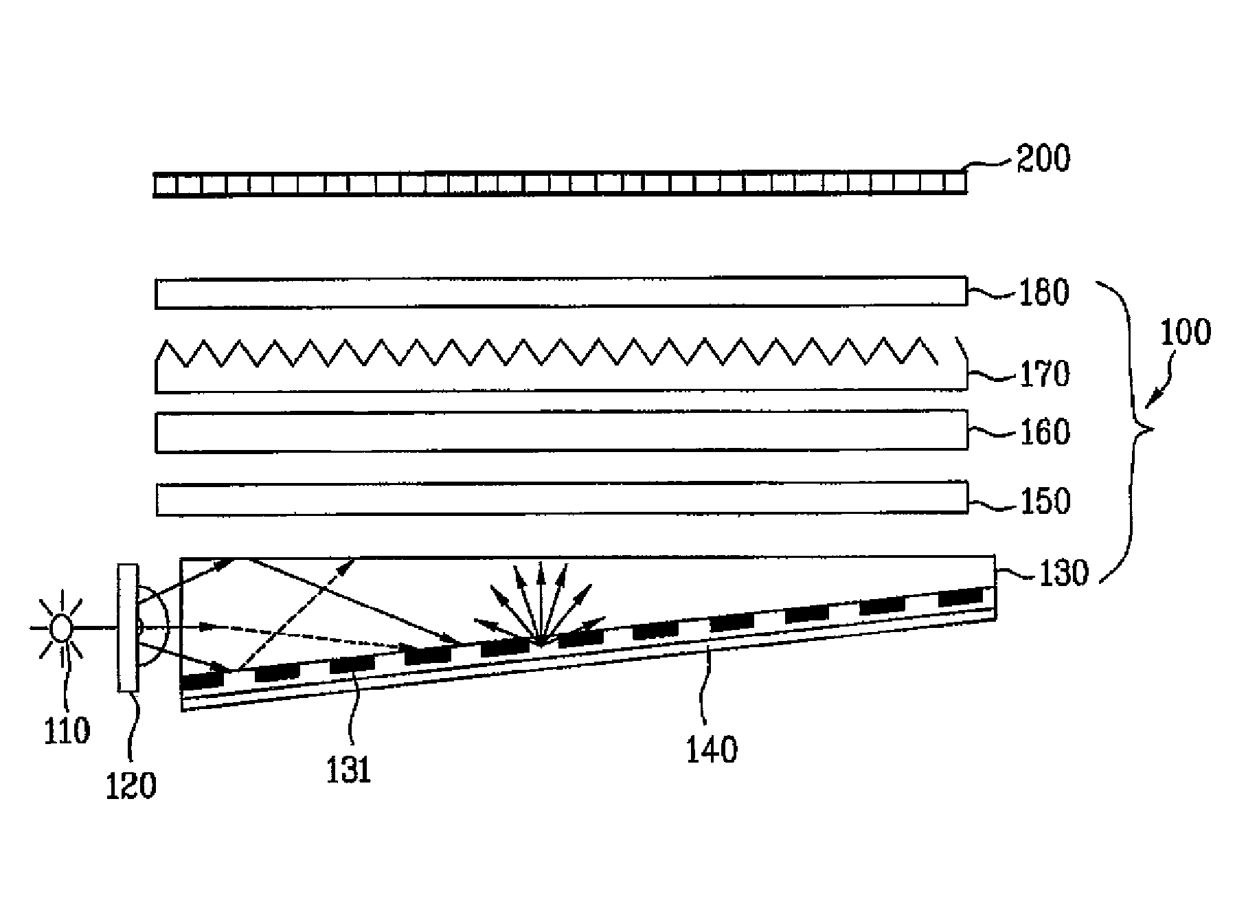
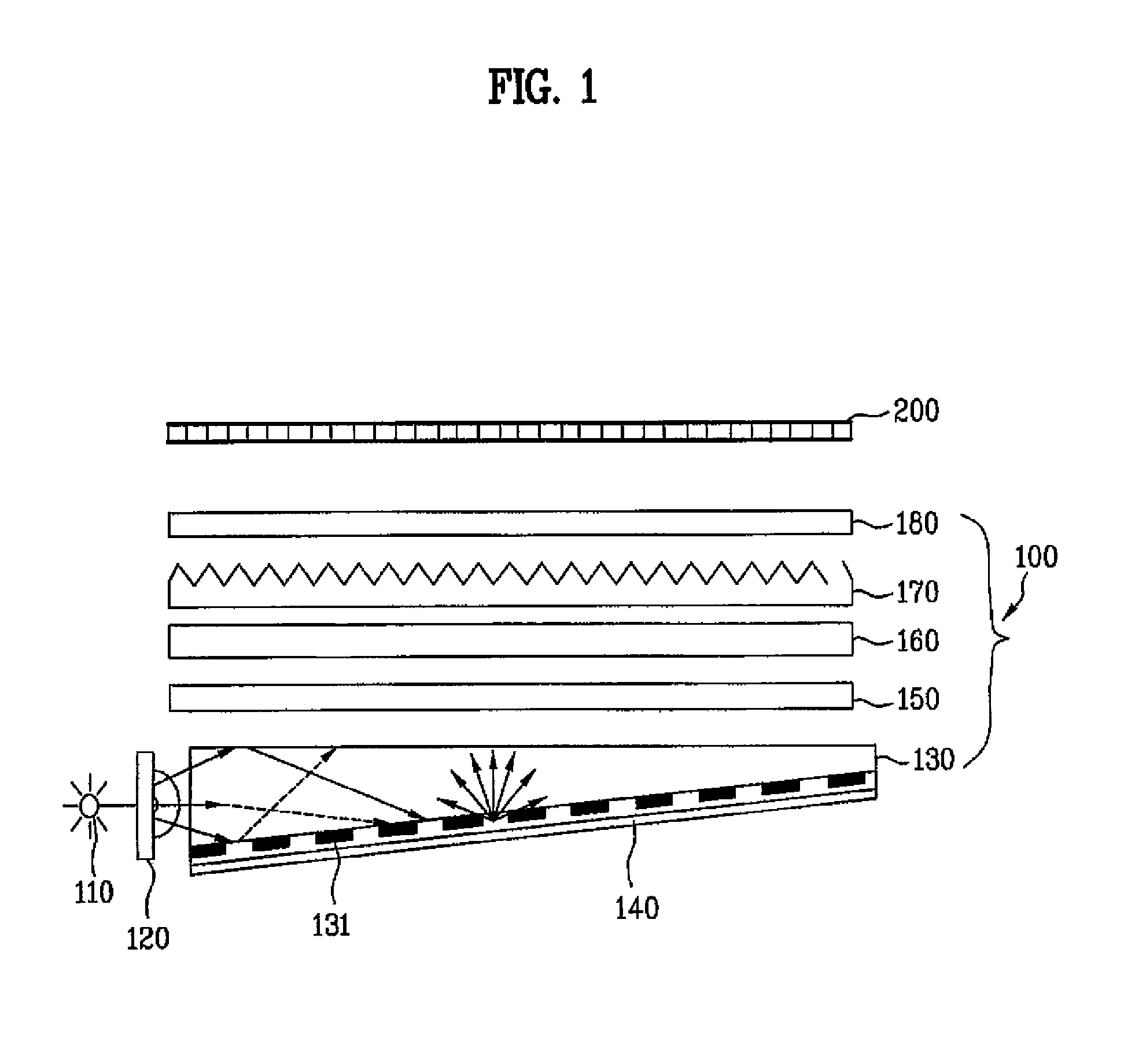
[0034]FIG. 1 is a configuration view illustrating a liquid crystal display according to an embodiment of the present invention.

[0035]As shown in FIG. 1, the liquid crystal display apparatus according to the present invention includes a back light unit (hereinafter, shortly referred to as “BLU”) 100, and a liquid crystal panel 200.

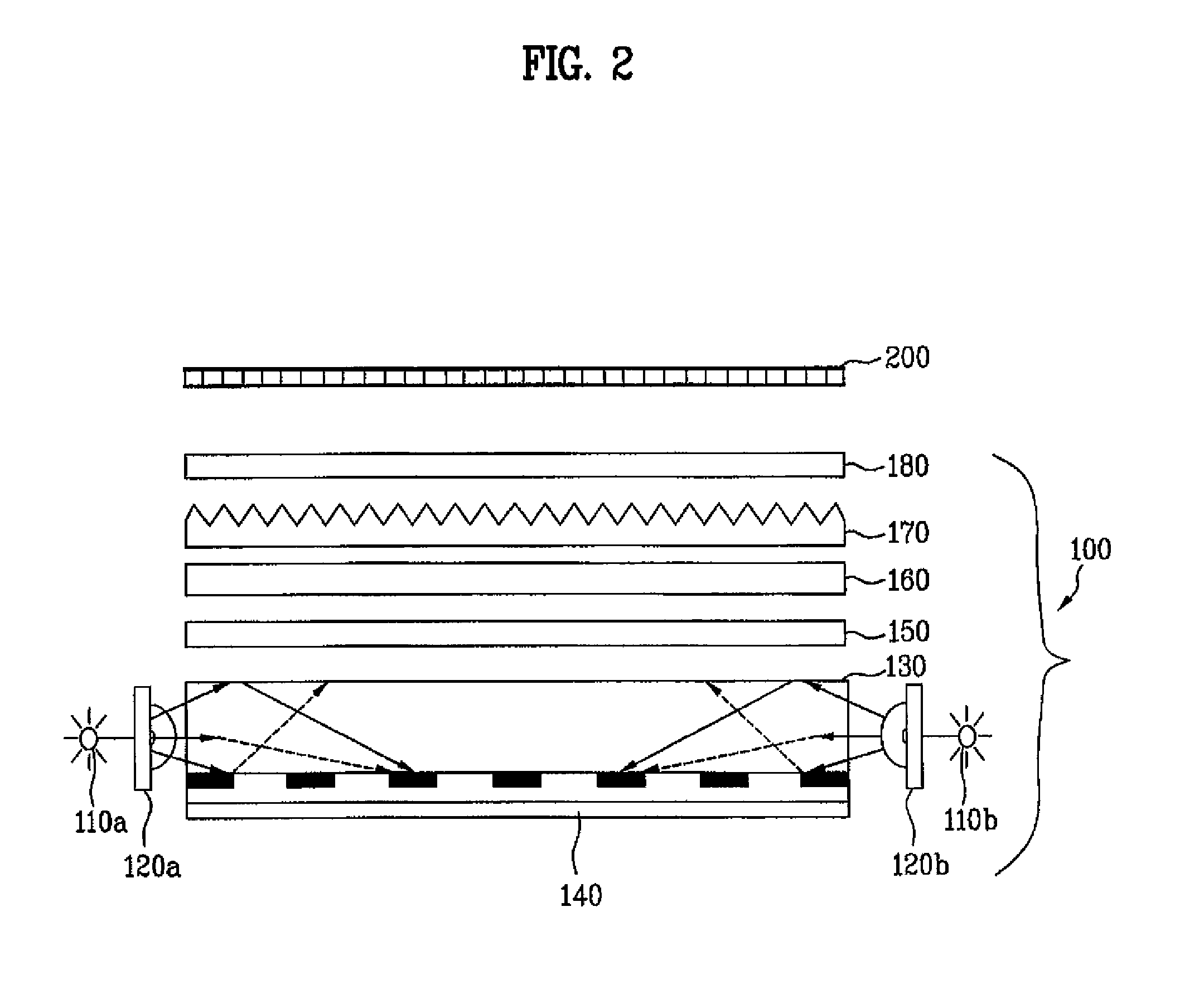
[0036]The BLU 100 includes a laser light source 110, a holographic diffuser 120, a light guide panel 130, first and second diffuser sheets 150 and 180, and first and second prism sheets 160 and 170.

[0037]It should be noted that two or more ones of the above constituent elements may be combined to constitute a single element, or any one of the constituent elements may be divided into...


PUM


Abstract

A back light unit is disclosed. The back light unit includes a laser light source having a superior system organization efficiency and color reproducibility, and achieves uniform illumination by diffusing laser beams onto a light guide panel.

Description

[0001]This application claims the benefit of the Korean Patent Application No. 10-2006-0110294 filed on Nov. 9, 2006, which is hereby incorporated by reference as if fully set forth herein.BACKGROUND OF THE INVENTION[0002]1. Field of the Invention[0003]The present invention relates to a back light unit, and more particularly, to a back light unit for a display apparatus.[0004]2. Discussion of the Related Art[0005]A liquid crystal display (hereinafter, shortly referred to as “LCD”) apparatus is configured to adjust a brightness and darkness by changing the arrangement of liquid crystals introduced into a liquid crystal panel, and to display an image as light beams penetrate the adjusted bright and dark regions.[0006]However, since the liquid crystal panel has no self-illumination function, the LCD includes a back light unit (BLU) to provide a rear surface of the liquid crystal panel with light beams.[0007]The BLU includes a light source, a light guide panel, a reflector sheet, first ...

Claims


Application Information

Patent Timeline
Patent Type & Authority Patents(United States)
IPC IPC(8): F21V7/04F21V7/22
CPCG02B5/0252G02B5/0278G02F1/133615G02B6/0025G02B6/0066G02B5/32G02F1/1335
Inventor PARK, SO YEONPARK, JONG MYOUNGSHIN, SUNG CHULKIM, YOUNG WOON
Owner LG ELECTRONICS INC
Learn More