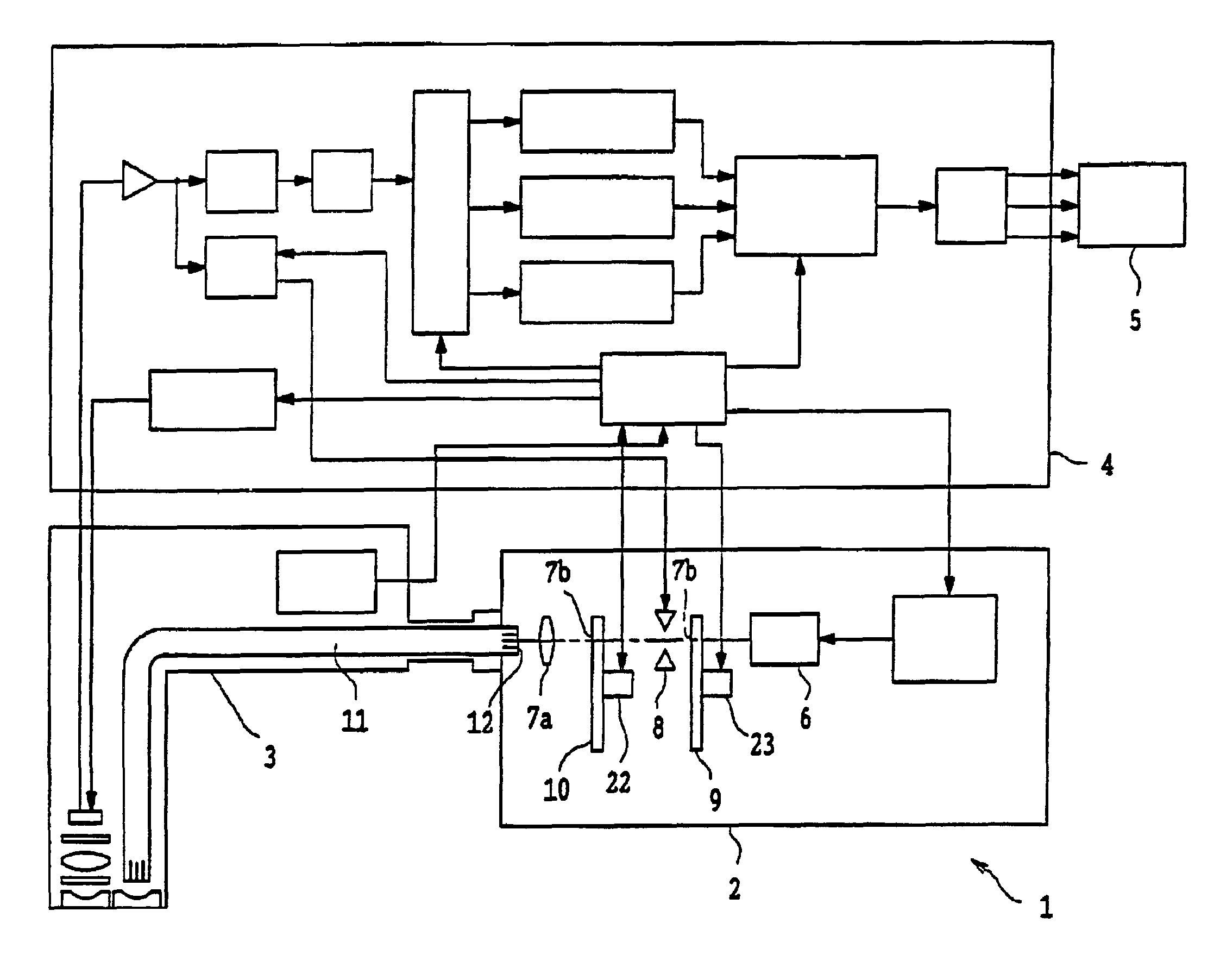
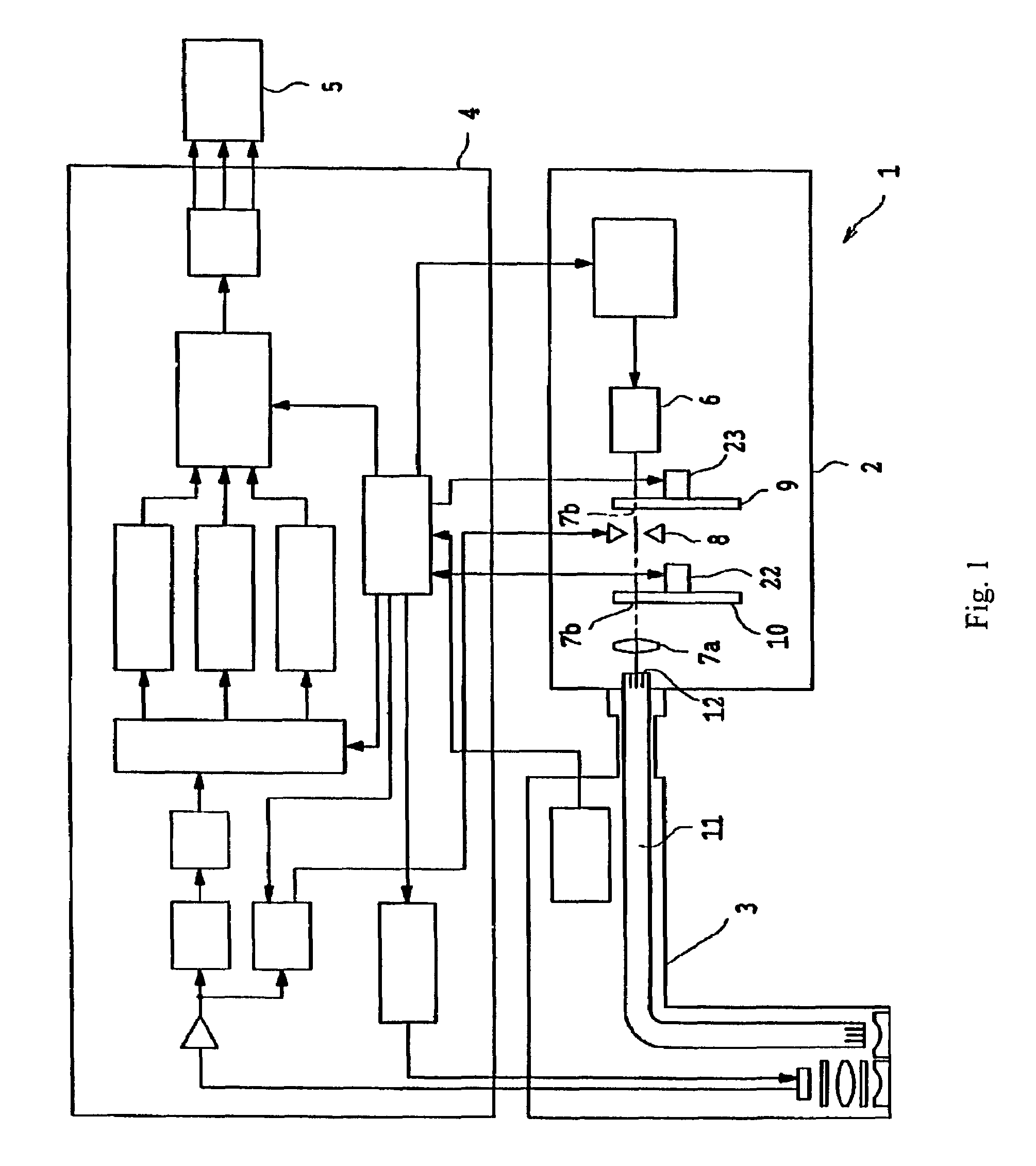
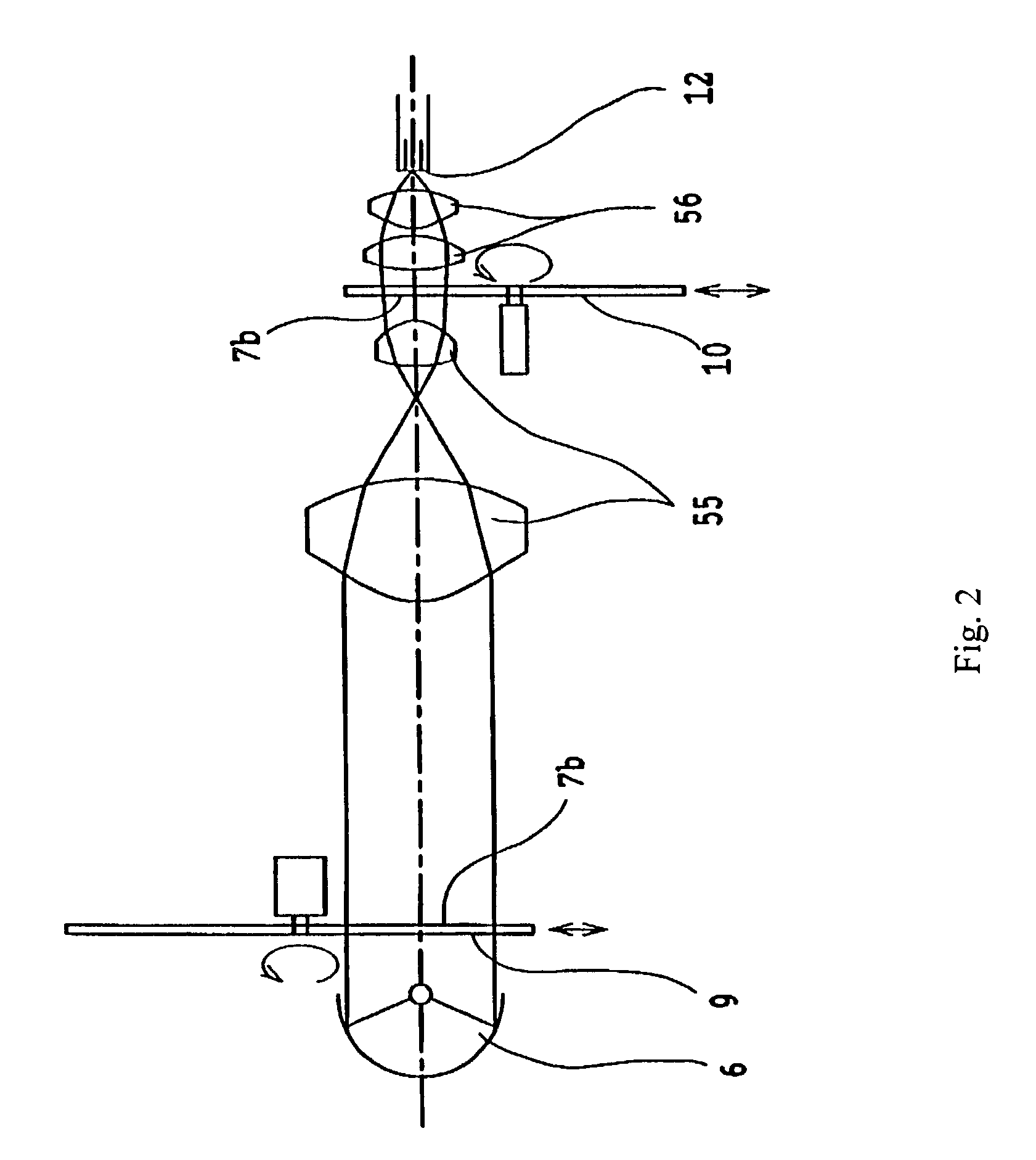
Endoscope that provides selection of each illumination mode of four different illumination modes

a technology of illumination mode and endoscope, which is applied in the field of endoscope, can solve the problems of increasing the time required for such an endoscopic examination, and the mention of correct diagnosis methods and apparatus, so as to achieve efficient work

Active Publication Date: 2010-04-27
OLYMPUS CORP
View PDF15 Cites 49 Cited by
  • Summary
  • Abstract
  • Description
  • Claims
  • Application Information

AI Technical Summary

Benefits of technology

[0005]The present invention relates to an endoscope for observing the interior of a coelom. More specifically, the present invention provides an endoscope and an endoscope diagnosing method which can efficiently perform the work of precisely diagnosing and treating a lesion by combining an ordinary color image observation and multiple special light observations.

Problems solved by technology

Because of this, there is a shortcoming in that it is troublesome to have to change the endoscope apparatus every time the kind of special light observation is changed, and such a procedure increases the time required for such an endoscopic examination.
However, there is no mention of a method and apparatus for diagnosing a lesion state correctly within a short period of time by combining special light observations.

Method used


Image

  • Endoscope that provides selection of each illumination mode of four different illumination modes
  • Endoscope that provides selection of each illumination mode of four different illumination modes
  • Endoscope that provides selection of each illumination mode of four different illumination modes

Examples


example 1

[0200]As a first example of a light amount adjusting means that may used in conjunction with the present invention, a DMD may be used as disclosed in U.S. Pat. No. 6,464,633,the subject matter of which is hereby incorporated by reference.

example 2

[0201]FIG. 41(a) is a top view, and FIG. 41(b) is an oblique view of a light amount adjusting means of Example 2.

[0202]The blades b1, b2, etc., have rotation axes and each blade is supported by an upper side support member and a lower side support member (not shown) at its top end and bottom end, respectively. As shown in FIG. 41(b), first and second driving members 201 and 202 are provided, with the right bottom corner of each blade fixed to the first driving member 201 and the left bottom corner of each blade fixed to the second driving member 202. The first and second driving members are slidable along parallel axes as shown by the double-headed arrows Y1 and Y2.

[0203]The light amount adjusting means is positioned in the light path of the illumination light from the light source such that a plane that is parallel to the rotation axes as well as the direction of motion of the first and second driving members is substantially perpendicular to the central axis of the illumination li...

example 3

[0207]FIG. 42 is a top view of a light adjusting means according to Example 3, and FIGS. 43(a)-43(e) are partial, top views for explaining the function of this example.

[0208]The light adjusting means of this example is provided with a first support frame 210 and a second support frame 220. The blades b1, b2, etc., each has a rotation axis on the side nearest the illumination, and these rotation axes are supported by the first support frame 210. The blades b1, b2, etc., are made of electrically conductive material and connected to circuitry (not shown in FIG. 42) via the rotation axes. The blades b1, b2, etc., are always charged with negative charges.

[0209]Electric insulator plates S1, S2, etc., are supported at their four corners by the first and second support frames 210 and 220 and positioned parallel with each other so as to be aligned with the illumination light (i.e., perpendicular to the support frames 210 and 220). Each of the electric insulator plates S1, S2, etc., is made o...


PUM

PropertyMeasurementUnit
wavelengthsaaaaaaaaaa
incidence angleaaaaaaaaaa

Abstract

An endoscope is disclosed that provide selection of each illumination mode of four different illumination modes, with one of the four different illumination modes being a mode which sequentially transmits very narrow wavelength ranges at three different wavelength regions within the visible spectrum.

Description

CROSS REFERENCE TO RELATED APPLICATION[0001]This application is related in subject matter to that of commonly assigned U.S. application Ser. No. 10 / 320,502, entitled “Endoscope”, filed Dec. 12, 2002. Also, this application claims the benefit of foreign priority from Japanese Patent Application No. 2002-164875, filed Jun. 5, 2002, the contents of which are hereby incorporated by reference.BACKGROUND OF THE INVENTION[0002]Endoscope apparatuses wherein a scope is inserted into a coelom in order to observe portions of the alimentary canal such as the esophagus, the stomach, the small intestine, and the large intestine, or into the trachea and the lungs for observing images on a TV monitor screen are commonly utilized. Recently, the use of illumination light of specific wavelength ranges for observing in vivo tissue has started to become popular. For example, an endoscope apparatus has been proposed for more easily identifying lesions that are difficult to discern with normal observation...

Claims


Application Information

Patent Timeline
Patent Type & Authority Patents(United States)
IPC IPC(8): A61B1/06A61B1/04H04N7/18G01N21/64A61B1/00A61B5/00G02B23/24G02B23/26
CPCA61B1/043A61B1/0638A61B1/0646A61B1/0669A61B5/0084G02B23/2469A61B5/0071
Inventor SUZUKI, TAKAYUKIHASEGAWA, AKIRAMATSUMOTO, SHINYA
Owner OLYMPUS CORP
Why Eureka
Try Eureka