Method of connecting and structure of connecting electric wire and connection terminal

a technology of connecting structure and electric wire, which is applied in the direction of connection formation by deformation, laser beam welding apparatus, manufacturing tools, etc., can solve the problems of explosive scattering, increase fabrication cost, and reduce welding strength or the like, and achieve stable welded state and high density energy

Inactive Publication Date: 2010-04-27
YAZAKI CORP
View PDF59 Cites 51 Cited by
  • Summary
  • Abstract
  • Description
  • Claims
  • Application Information

AI Technical Summary

Benefits of technology

[0016]An object of the invention relates to resolving the above-described problem and provides an excellent method of connecting and an excellent structure of connecting an electric wire and a connection terminal capable of stably ensuring an electric resistance and a mechanical strength of the connection terminal and the electric wire without increasing cost of the connection terminal.
[0019]According to the method of connecting and the structure of connecting the electric wire and the connection terminal having the above-described constitution, the connection terminal and the electric wire are welded to connect by irradiating the laser beam from above the wire caulking portion of the connection terminal, a metallic bonding portion is formed between the connection terminal and the electric wire and therefore, the electric resistance and the mechanical strength can stably be ensured.
[0021]However, laser beam irradiated portions at the second time and thereafter are set such that a welded region thereof overlaps a welded portion of the laser beam irradiated portion immediately previously, laser irradiation is carried out within a time period in which a state of elevating a temperature by irradiating the laser beam immediately previously remains and therefore, rapid heating is not constituted by heating by irradiating laser beam at the second time and thereafter, the material is gradually melted and therefore, explosive scattering caused by rapid boiling can be prevented from being brought about.
[0023]Hence, even when materials (physical properties) of the connection terminal and the electric wire differ from each other and laser beam having a high density energy matched to a material having large heat of melting needs to be irradiated, a stable welded state can be achieved by preventing explosive scattering from being brought about and an excellent connected state between the connection terminal and the electric wire conductor can be maintained over a long period of time.

Problems solved by technology

Therefore, there poses a problem that many kinds of press contact terminals having dimensions of C / W and C / H matched to respective sizes of electric wires and respective kinds of terminals need to prepare and caulking operation needs to control to thereby increase fabrication cost.
However, according to the above-described connecting method, as shown by FIG. 7, there poses a problem that a terminal material melted by irradiating the laser beam 9 is absorbed by clearances of the conductor 3 and a large recess 13 is produced at a laser welded portion 11 to thereby reduce welding strength or the like.
Further, in laser welding, the welding is carried out by irradiating the laser beam having high density energy and therefore, rapid heating or rapid boiling of the terminal material and the conductor is brought about which may bring about explosive scattering (splash phenomenon).
However, when the electric wire and the connection terminal are connected by laser welding described in JP-A-6-302341 and JP-A-2000-231944, mentioned above, and the like, as described above, the projected portion or the thick-walled portion for replenishing the welded volume needs to provide at the wire caulking portion of the connection terminal, or the irradiation port for irradiating laser beam needs to form at inside of the press contact portion of the connection terminal to thereby pose a problem of increasing working steps in fabricating the connection terminal or increasing cost of the connection terminal owing to complicated formation of a die for pressing a connection terminal.
Whereas a melting point and heat of melting of aluminum are 660° C. and 94.5 cal / g, and a melting point and heat of melting of copper are 1083° C. and 50.6 cal / g and physical properties thereof differ from each other significantly and therefore, it is difficult to ensure excellent connection function by applying laser welding, mentioned above.

Method used


Image

  • Method of connecting and structure of connecting electric wire and connection terminal
  • Method of connecting and structure of connecting electric wire and connection terminal
  • Method of connecting and structure of connecting electric wire and connection terminal

Examples


examples

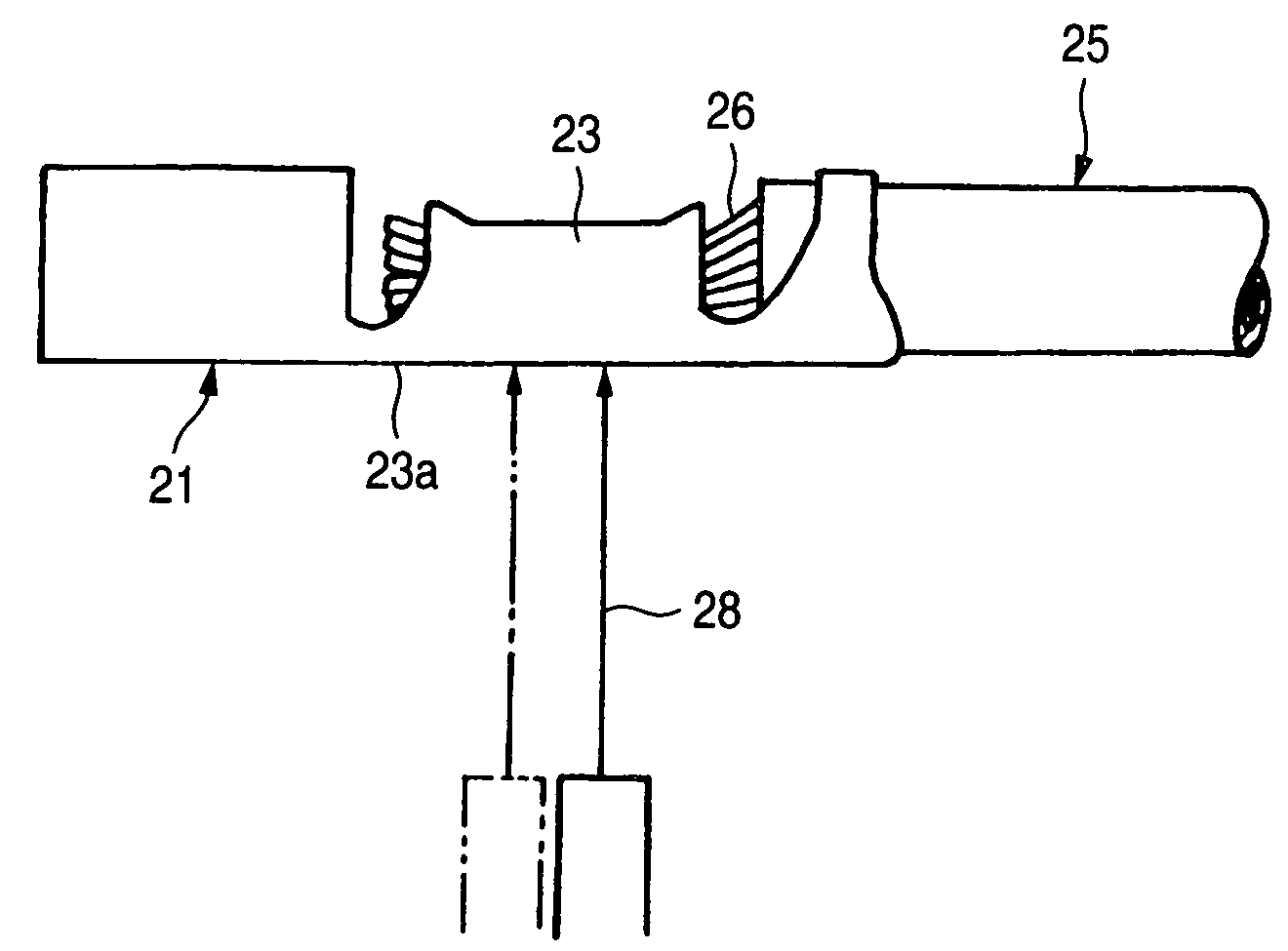
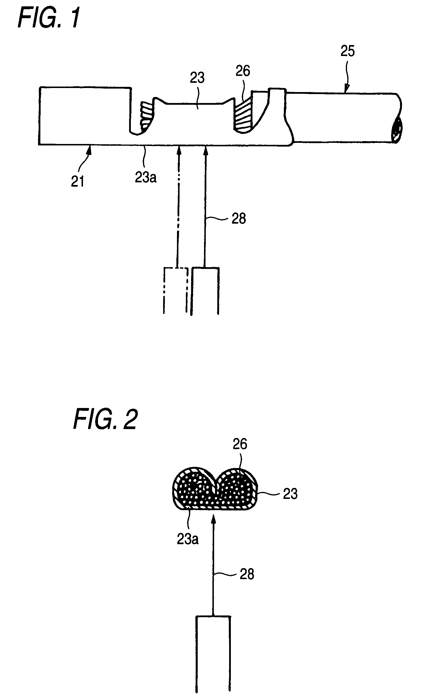
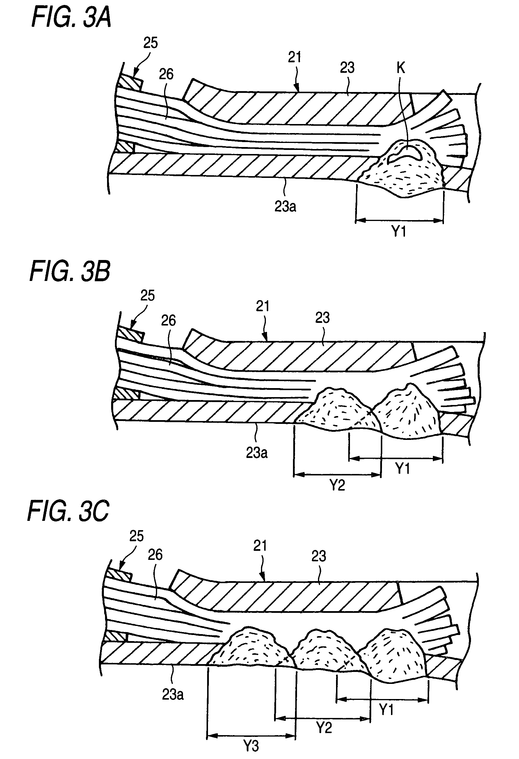
[0051]Next, a connection terminal according to the invention (Embodiment), which is connected with a conductor of an electric wire by crimping and subsequently performing three times of laser irradiation as described above, and a connection terminal (Comparative Example), which is connected with a conductor of an electric wire only by crimping in the same manner as Embodiment and no laser irradiation is conducted, are subjected to two durability tests. The comparison in performance of the connection terminals at the initial states and after subjected the durability tests (Durability Test 1 and Durability Test 2) respectively is illustrated in a graph of FIG. 4.

[0052]Further, a Cu alloy is used for the respective connection terminals and an aluminum series conductor is used for the respective conductors.

[0053]In this case, Durability Test 1 is a high temperature leaving test for leaving samples (10 pieces respectively) in a high temperature environment at 120° C. for 120 hours and re...


PUM

PropertyMeasurementUnit
melting pointaaaaaaaaaa
temperatureaaaaaaaaaa

Abstract

After bringing a conductor of an electric wire into press contact to connect with a wire caulking portion of a connection terminal, the conductor and the wire caulking portion are welded to connect by irradiating laser beam to a bottom wall of the wire caulking portion. Laser irradiation is carried out intermittently by three times and the laser irradiation at the second time and thereafter which is carried out later is carried out such that during a time period in which a laser welded portion immediately previously is brought into a predetermined state of elevating temperature, portions or welded regions overlap welded regions in laser irradiation irradiated previously.

Description

[0001]This application is a divisional of application Ser. No. 10 / 732,269 filed Dec. 11, 2003.[0002]The present application is based on Japanese Patent Application No. 2002-359486, the entire contents of which are incorporated herein by reference.BACKGROUND OF THE INVENTION[0003]1. Field of the Invention[0004]The present invention relates to a method of connecting and a structure of connecting an electric wire and a connection terminal for bringing a conductor of an electric wire into press contact to connect with a wire caulking portion of a connection terminal and thereafter welding to connect the conductor and the connection terminal by laser welding.[0005]2. Related Art[0006]Conventionally, as a method of connecting an electric wire and a connection terminal, there is spread a method of electrically connecting an electric wire and a connection terminal by bringing a wire caulking portion mounted to the connection terminal into press contact to connect to caulk on a conductor of ...

Claims


Application Information

Patent Timeline
Patent Type & Authority Patents(United States)
IPC IPC(8): H01R4/02B23K26/42H01R4/18H01R43/02
CPCH01R43/0221H01R4/185Y10T29/49179Y10T29/49185
Inventor ASAKURA, NOBUYUKIFUJIMOTO, KEIONUMA, MASANORI
Owner YAZAKI CORP
Why Eureka
Try Eureka