
Apparatus and method for testing magnetic disk drive components using drive-based parts

a technology of magnetic disk drives and components, applied in the field of data storage devices, can solve the problems of low correlation between the analog test measurement of components obtained with conventional testers and the actual performance of disk drives, and the use of conventional component testing machines to test drive components is very expensive, etc., to achieve high tpi densities, high accuracy, and high efficiency

Inactive Publication Date: 2010-04-27
SEAGATE TECH LLC
View PDF6 Cites 11 Cited by
  • Summary
  • Abstract
  • Description
  • Claims
  • Application Information

AI Technical Summary

Benefits of technology

"The present invention is an apparatus and method for testing components of a magnetic disk drive using drive-based components that are based on components of an actual magnetic disk drive. The tester is faster, less expensive, and more accurate than conventional testers. It can test various different components of the magnetic disk drive and is capable of testing with higher accuracy and higher TPI densities. The tester provides a testing environment for components that is much closer to that of an actual disk drive. The use of drive-based components allows the tester to perform high-precision, high-bandwidth track positioning during testing with no long-term position drift."

Problems solved by technology

However, the use of conventional component testing machines to test drive components is very costly due to their complicated electrical and mechanical designs.
Conventional testers typically have used expensive precision, custom-made components such as mechanical positioning stages, stepper motors, discrete channels, air-bearing spindle motors and motor plate mechanics.
In addition, conventional testers have been typically designed with little consideration of the disk drive environment.
Thus, conventional testers did not test components in an environment similar to that of an actual disk drive.
As a result, the correlation between the analog test measurements of components obtained with conventional testers and their actual performance in disk drives has been relatively low.
This low correlation resulted in relatively high levels of over-rejects and false acceptance of components.
Another disadvantage of conventional testers is that they relied on mechanical positioners to place the head on the written track instead of using a servo control loop.
This limited the track control or tracks per inch (TPI) capabilities of these testers.
Further, the positioners were not be able to support track-following of high-frequency track misregistration (TMR) because of the low bandwidth inherent to their large mass and size.

Method used


Image

  • Apparatus and method for testing magnetic disk drive components using drive-based parts
  • Apparatus and method for testing magnetic disk drive components using drive-based parts
  • Apparatus and method for testing magnetic disk drive components using drive-based parts

Examples


Embodiment Construction

[0027]The detailed description set forth below in connection with the appended drawings is intended as a description of various embodiments of the present invention and is not intended to represent the only embodiments in which the present invention may be practiced. The detailed description includes specific details for the purpose of providing a thorough understanding of the present invention. However, it will be apparent to those skilled in the art that the present invention may be practiced without these specific details. In some instances, well-known structures and components are shown in block diagram form in order to avoid obscuring the concepts of the present invention.

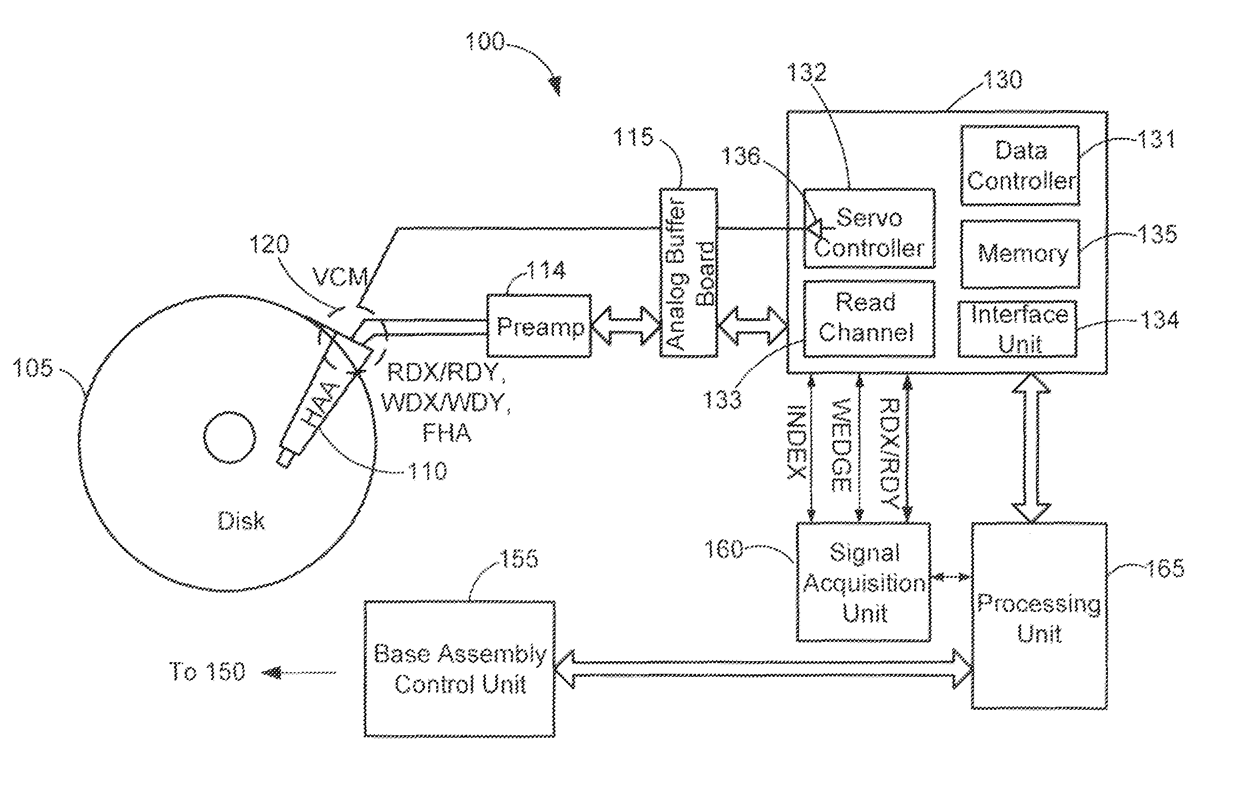
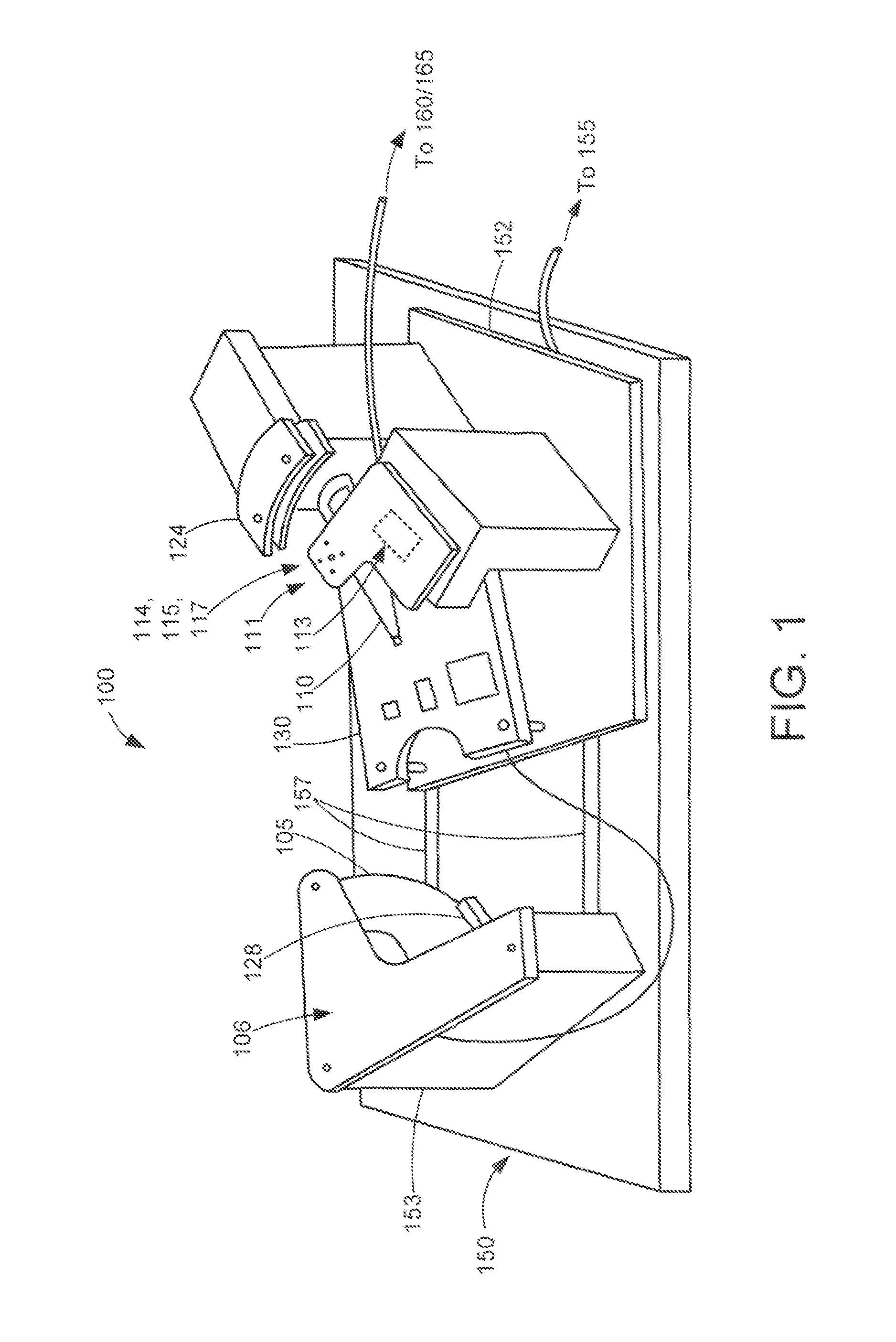
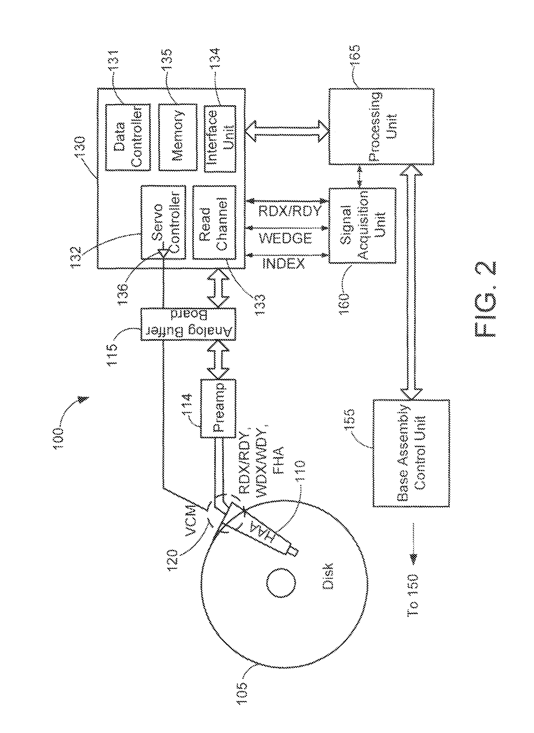
[0028]FIGS. 1 and 2 show a magnetic disk drive component tester 100 in accordance with one embodiment of the present invention. FIGS. 1 and 2 respectively depict in simplified form a perspective drawing and a block diagram of the tester 100. The tester 100 is used to perform parametric tests on a disk drive co...


PUM


Abstract

An apparatus and method for testing a component of a magnetic disk drive in which one or more drive-based components is used in the testing process. Each of the drive-based components is based on a corresponding one of the components of the magnetic disk drive. During testing, the component to be tested and at least one of the drive-based components are selectively engaged.

Description

CROSS-REFERENCE TO RELATED APPLICATIONS[0001]The present application claims priority from U.S. Provisional Patent Application Ser. No. 60 / 616,243 filed on Oct. 6, 2004 entitled “APPARATUS FOR TESTING HARD DISK DRIVE COMPONENTS FOR TIMING, READING, WRITING, MOTOR CONTROL AND SERVO POSITIONING USING PRODUCTION PARTS” and from U.S. Provisional Patent Application Ser. No. 60 / 616,244 filed on Oct. 6, 2004 entitled “LIGHTWEIGHT HDD ACTUATOR ARM TO HGA ATTACHMENT DEVICE FOR HDD COMPONENT TESTER,” the entirety of which are incorporated herein by reference.BACKGROUND OF THE INVENTION[0002]The present invention relates generally to data storage devices and more specifically, to apparatus and methods for testing components of magnetic disk drives.[0003]Magnetic disk drives are typically composed of components such as read / write heads, actuators, magnetic disks, spindle motors, printed circuit board assemblies and firmware. These components are tested during manufacturing using one or more comp...

Claims


Application Information

Patent Timeline
Patent Type & Authority Patents(United States)
IPC IPC(8): G01R33/12
CPCG11B5/455G11B27/36G11B20/1816G11B5/4555
Inventor EATON, ROBERTLIN, GANG HERBERTLIN, TAOCOMPANIEH, AMIR ALIMILBY, ROBCARROLL, RONKIMBALL, ROBERT
Owner SEAGATE TECH LLC
Learn More