Supercharge Your Innovation With Domain-Expert AI Agents!

Optical systems for microarray scanning

a microarray and optical system technology, applied in the direction of optical elements, optical resonator shape and construction, instruments, etc., can solve the problems of difficult optical system design, loss of laser light energy, and significant background problems of light reflecting from glass slides

Active Publication Date: 2010-04-27
CAPITALBIO CORP +1
View PDF18 Cites 30 Cited by
  • Summary
  • Abstract
  • Description
  • Claims
  • Application Information

AI Technical Summary

Benefits of technology

The solution increases the efficiency of the optical system, reduces background noise, and improves the signal-to-noise ratio by minimizing light loss and eliminating interference between excitation and emission light, while allowing for flexible use with different excitation light sources.

Problems solved by technology

There are several drawbacks associated with traditional optical systems.
First, incoming laser light loses energy by passing through the beam splitter.
Second, the glass surface of a traditional microarray chip usually reflects 1% or more of the incoming excitation light, which also enters the detection light path.
Because in most microarray detection experiments the intensity of the emission light is millions of times weaker than the light intensity of the excitation laser light, light reflected from the glass slide poses significant background problems.
This makes the design of the optical system difficult.

Method used


Image

  • Optical systems for microarray scanning
  • Optical systems for microarray scanning
  • Optical systems for microarray scanning

Examples


Embodiment Construction

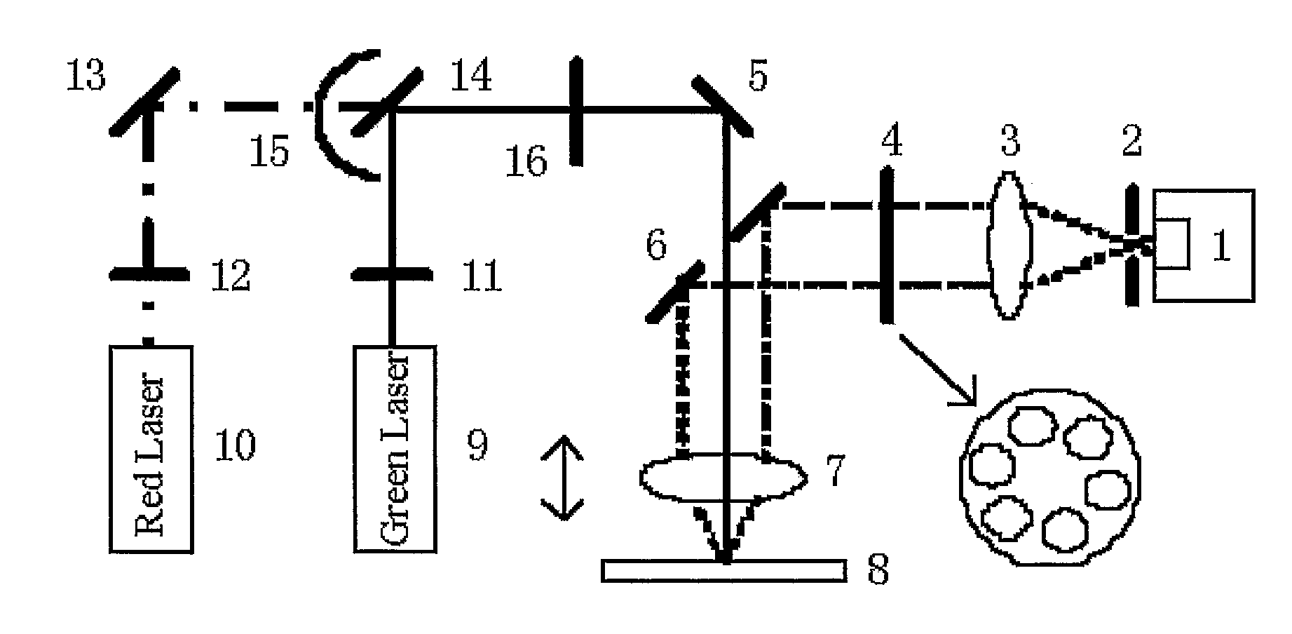
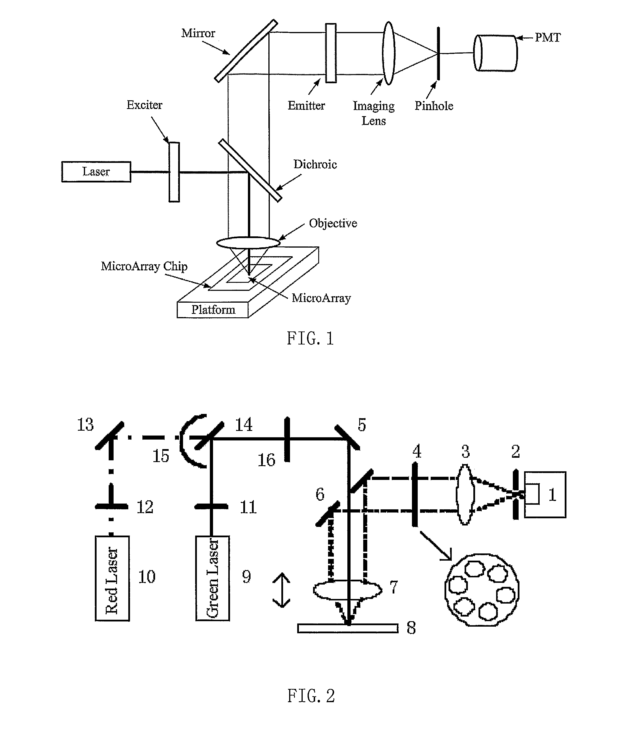
[0016]The present invention provides a novel optical system for microarray analysis that provides high sensitivity, low background noise, and relative simple structure. The optical system comprises an aperture-containing reflecting mirror, which comprises an aperture that allows an excitation light to directly pass through and a reflecting surface that allows emission light from a microarray to be reflected. In some embodiments, the optical system may further comprise an excitation objective lens for focusing the excitation light passing through the aperture of the aperture-containing reflecting mirror and / or collimating emission light from the microarray. In some embodiments, the excitation objective lens is connected to a motor (such as a stepper motor), which moves the objective lens in a direction perpendicular to the surface of the microarray. The position of the objective lens can thus be adjusted in order to focus the excitation light.

[0017]Use of the aperture-containing refl...


PUM


Abstract

The invention provides a novel optical system for use in a microarray scanner, comprising an aperture-containing reflecting mirror comprising an aperture and a reflecting surface. The aperture of the aperture-containing reflecting mirror allows an excitation light to pass through, and the reflecting surface of the aperture-containing reflecting mirror allows emission light from a microarray to be reflected. The optical system may also comprises various other components such as laser generators, beam splitter, reflecting mirrors, excitation and emission light filters, excitation and emission objective lens, pinhole, and detector. The optical system described herein has high efficiency, high sensitivity, low background noise, structurally simple, and high versatility.

Description

TECHNICAL FIELD[0001]This application is in the field of optical systems used in microarray scanning.BACKGROUND OF THE INVENTION[0002]Developments in microarray-based detection devices have dramatically changed the biotechnology industry. The devices make it possible to analyze multiple biological samples simultaneously and detect rare transcripts in human. They also make it possible to obtain information from microarrays automatically within minutes instead of within months or even years without the help of the devices.[0003]Microarrays typically comprise a plurality of polymers, such as oligonucleotides, peptides, and antibodies. The polymers are synthesized or deposited on a substrate in an array pattern, which can be labeled with optically detectable labels such as fluorescent tags or fluorophores. A typical microarray scanner uses laser as excitation light source, and use matching filters and photomultiplier tubes for detection. During scanning of a microarray, excitation light...

Claims


Application Information

Patent Timeline
Patent Type & Authority Patents(United States)
IPC IPC(8): H01S3/10
CPCG02B21/002G01N21/6452
Inventor WANG, XIANHUAHUANG, GUOLIANGCHENG, JINGZHANG, HONGGAO, TAISHAN
Owner CAPITALBIO CORP
Features
  • R&D
  • Intellectual Property
  • Life Sciences
  • Materials
  • Tech Scout
  • Unparalleled Data Quality
  • Higher Quality Content
  • 60% Fewer Hallucinations
Learn More