Heat generator for screen deployment

a heat generator and screen technology, applied in the field of downhole screens, can solve the problems of large annular space outside the screen, risk of sticking the fixed swage, and the screen expansion technique as a replacemen

Active Publication Date: 2010-05-04
BAKER HUGHES INC
View PDF30 Cites 30 Cited by
  • Summary
  • Abstract
  • Description
  • Claims
  • Application Information

AI Technical Summary

Problems solved by technology

Problems arose with the screen expansion technique as a replacement for gravel packing because of wellbore shape irregularities.
Problems still included that a washout in the wellbore would still leave a large annular space outside the screen.
Conversely, a tight spot in the wellbore could create the risk of sticking the fixed swage.
On the other hand, if there was a void area, the same problem persisted in that the flexible swage had a finite outer dimension to which it would expand the screen.
Therefore, the use of flexible swages still left the potential problem of annular gaps outside the screen with a resulting undesired production of solids when the well was put on production from that zone.
If the compliant layer experiences too much heating in advance of placement, it will deploy prematurely, and in most cases be difficult or impossible to dislodge.
A difficulty with supplying heat downhole by injecting a heated medium is that the heat will be dissipated during transmission and insufficient heat will be delivered to the desired site.
Methods are known for providing heat only locally downhole, but they each have difficulties.
Downhole heaters, such as electrically-powered heaters, such as a wireline deployed electric heater, or a battery fed heater, may generally lack sufficient power (amperage) to provide the necessary heat for deployment.
However, most exothermic oxidation / combustion reactions require temperatures that would compromise mud stability, if not tubular integrity, and would tend to be difficult to initiate and would be problematic to formulate as a liquid or mud for downhole use.
Hydration of acidic electrolytes (such as aluminum chloride, AlCl3) or acids would also generate heat, but would be expected to be corrosive and at high temperatures could compromise the integrity of the tubular goods, tools, screens and other equipment in many circumstances.
While this operation can be accomplished by those skilled in the art, unforeseen circumstances can cause last minute disruptions to this scheduled treatment, and the heat can be liberated in an undesired location in the wellbore.

Method used


Image

  • Heat generator for screen deployment
  • Heat generator for screen deployment
  • Heat generator for screen deployment

Examples


Embodiment Construction

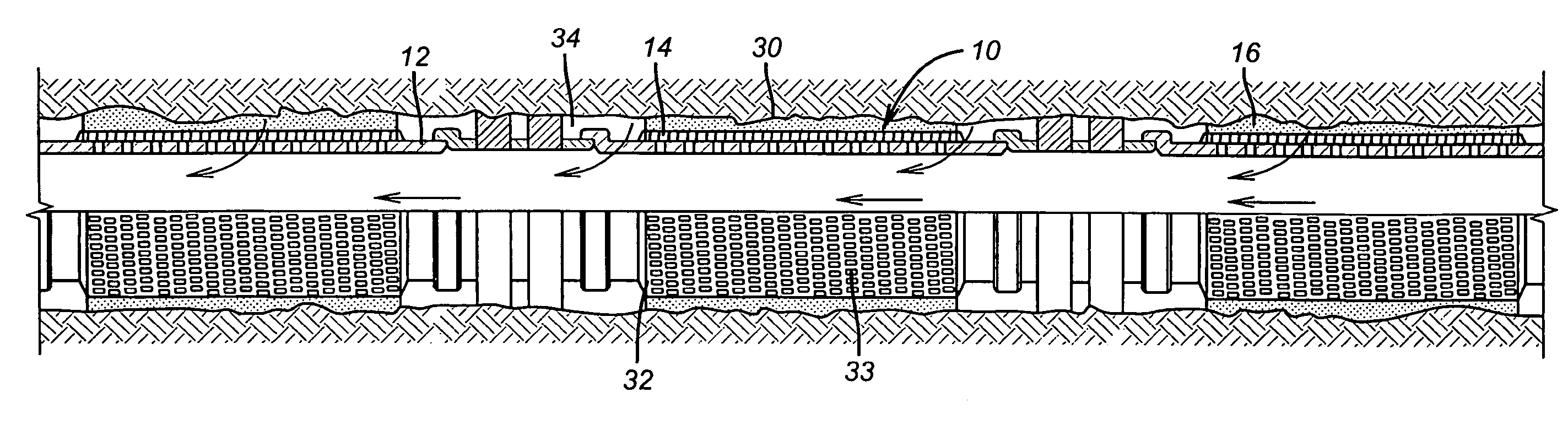
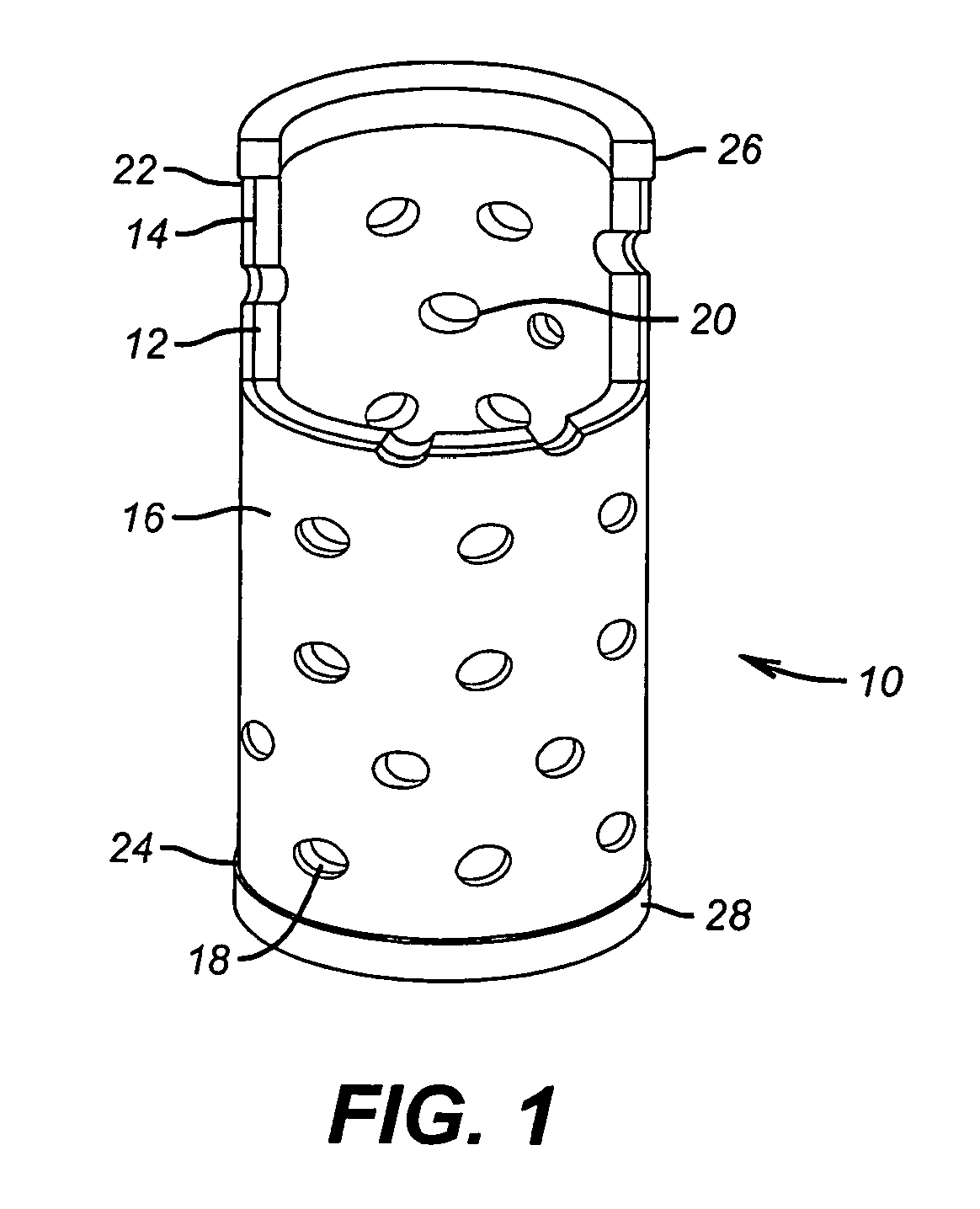
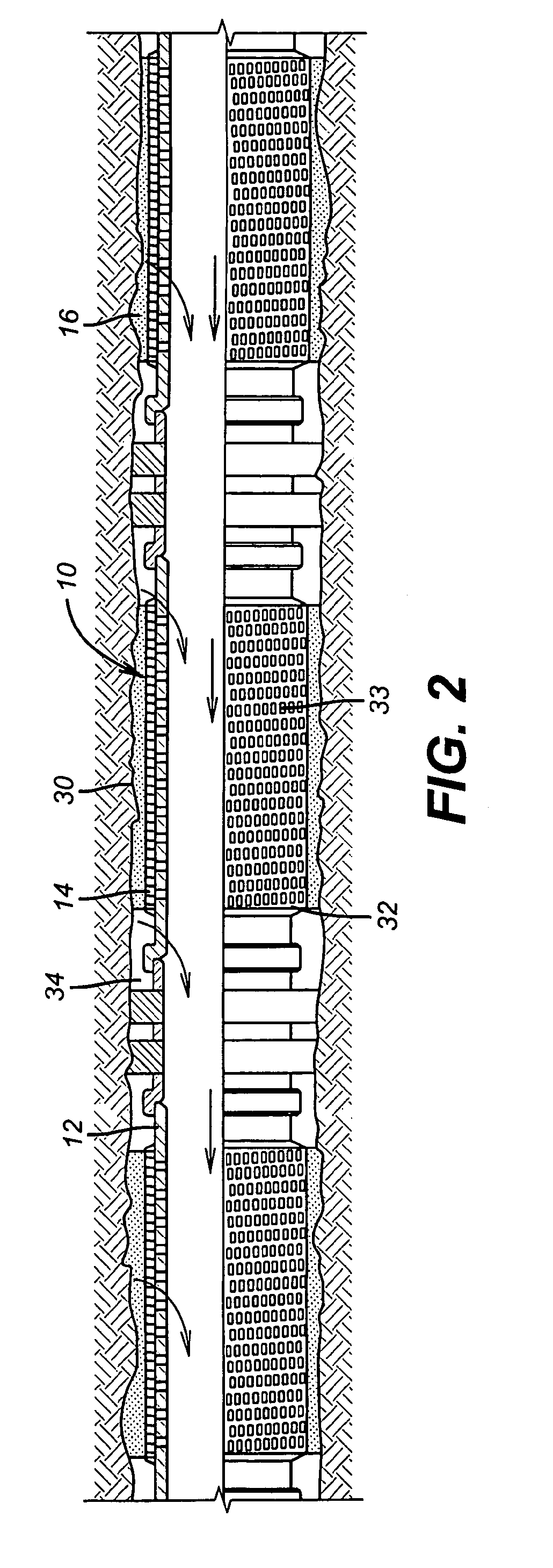
[0014]It has been discovered that a novel chemical catalyst system may deploy a shape memory foam screen to accomplish the purpose of expanding the screen to bridge an annular gap to a wellbore wall at a relatively precise downhole location. The simplicity and heat generated locally make it a much more attractive alternative than conventional downhole heating devices that lack sufficient amperage to produce the required heat for deployment, or where the heat dissipates from the surface to the deployment site.

[0015]The apparatus and method herein addresses the task of providing a sand control screen downhole by providing a screen assembly with an outer layer that can conform to the borehole shape upon expansion. In one non-limiting embodiment, a material is selected that will swell, expand, enlarge or otherwise deploy to further promote filling the void areas in the borehole after expansion. In an alternative design, screen expansion is not required and the outermost layer swells to ...


PUM


Abstract

A screen assembly has a material that conforms to the borehole shape after insertion. The assembly comprises a compliant layer that takes the borehole shape on expansion. The outer layer is formed having holes to permit production flow. The selected conforming material swells with heat, and in one non-limiting embodiment comprises a shape memory foam that is thermoset or thermoplastic. Heat is provided by supplying a fuel (including an oxidant) to a catalyst in close proximity to the compliant layer so that the product from the catalytic reaction is heated steam which contacts and deploys the conforming material. The base pipe can have a screen over it to act as an underlayment for support of the conforming layer or alternatively for screening.

Description

TECHNICAL FIELD[0001]The present invention relates to downhole screens, and more particularly relates, in one non-limiting embodiment, to downhole screens that can be expanded or deployed in response to locally applied heat.TECHNICAL BACKGROUND[0002]In the past, sand control methods have been dominated by gravel packing outside of downhole screens. The idea was to fill the annular space outside the screen with sized gravel to prevent the production of undesirable solids (sand) from the formation. More recently, with the advent of tubular expansion technology, it was thought that the need for gravel packing could be eliminated if a screen or screens could be expanded in place to eliminate the surrounding annular space that had heretofore been packed with gravel. Problems arose with the screen expansion technique as a replacement for gravel packing because of wellbore shape irregularities. A fixed swage would expand a screen only a fixed amount. Problems still included that a washout ...

Claims


Application Information

Patent Timeline
Patent Type & Authority Patents(United States)
IPC IPC(8): E21B43/24
CPCE21B36/008E21B43/08E21B36/02
Inventor RICHARD, BENNETT M.MCELFRESH, PAUL M.
Owner BAKER HUGHES INC
Why Eureka
Try Eureka