
Brake support structure

a support structure and brake technology, applied in the direction of braking systems, braking components, cycle equipment, etc., can solve the problems of difficulty in providing a space for the curvature around the pivot shaft, disadvantages as to cost and weight, etc., to achieve neat appearance and piping protection, convenient placement, and cost-saving

Inactive Publication Date: 2010-05-04
HONDA MOTOR CO LTD
View PDF23 Cites 11 Cited by
  • Summary
  • Abstract
  • Description
  • Claims
  • Application Information

AI Technical Summary

Benefits of technology

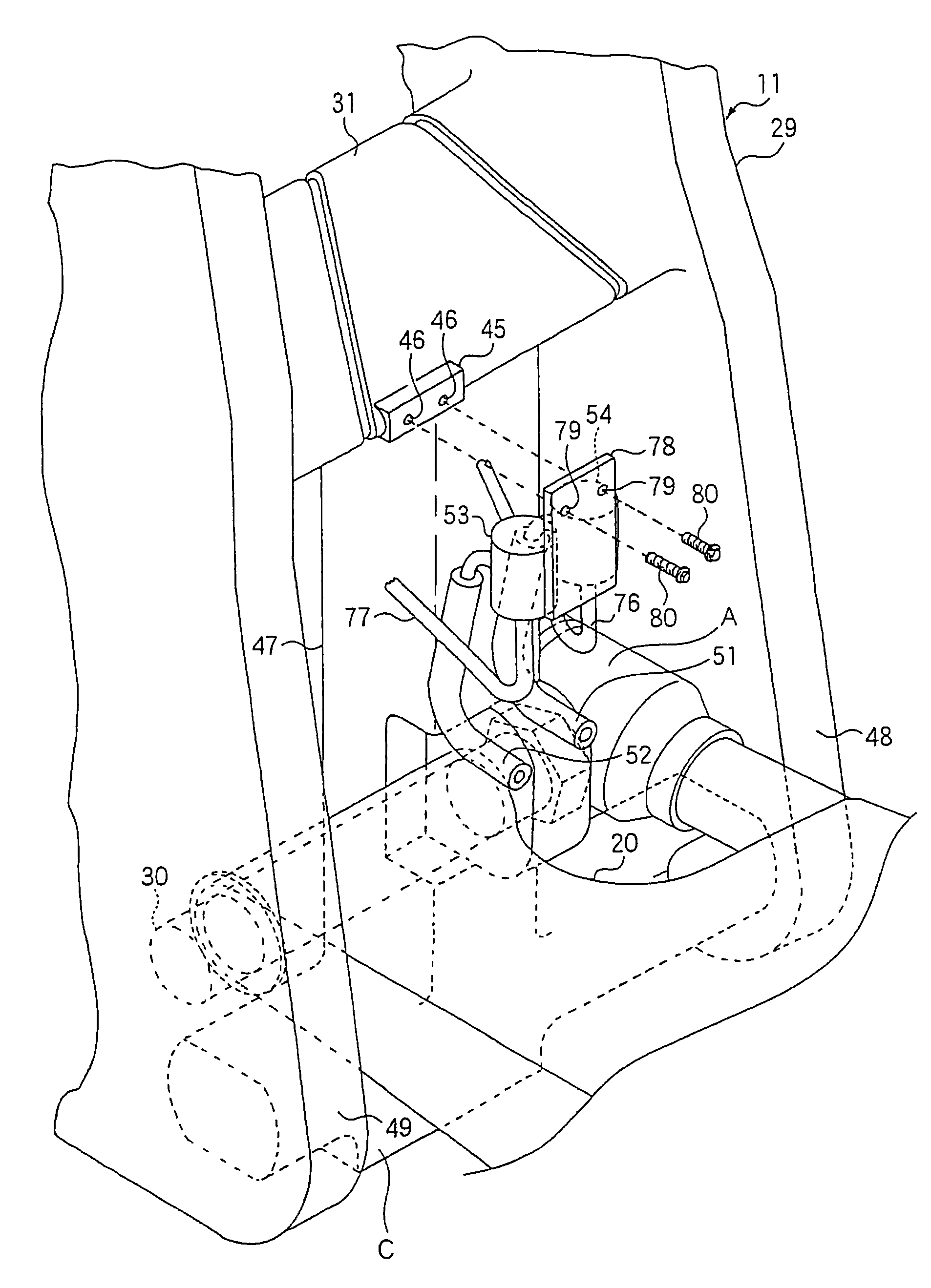
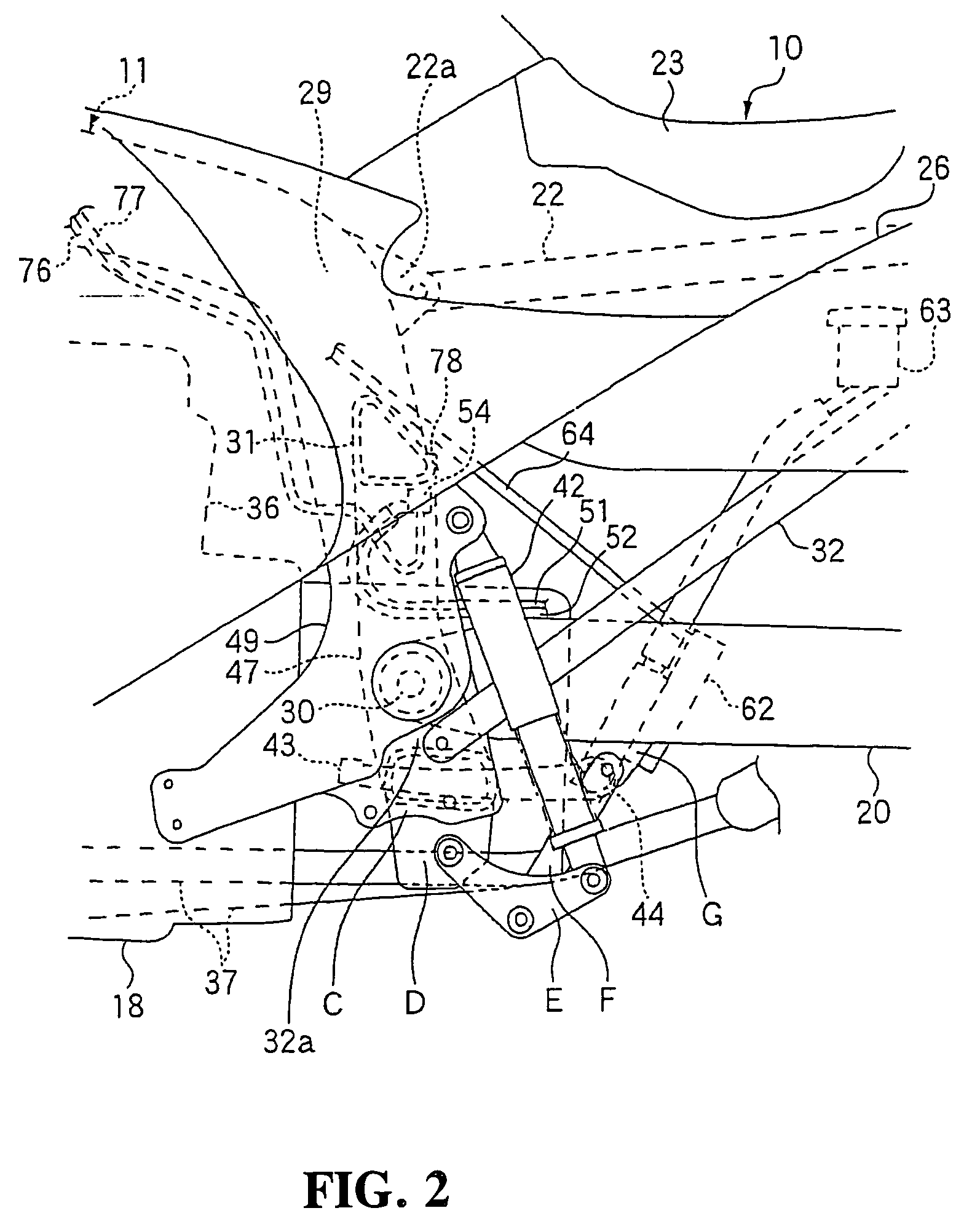
[0014]With the brake support structure according to an embodiment of the present invention, the cross member interconnecting the rear frames is disposed near the swing arm. The brake pipes connected to the brake caliper for braking the rear wheel extend between the cross member and the swing arm. Therefore, the dead space between the cross member and the swing arm is effectively utilized, allowing the brake piping to be easily placed around the pivot shaft and to have a layout for a neat appearance and piping protection. The brake support structure is advantageous as to cost and weight because there is no need for the installation of the separate pipe stay in the past.
[0015]With the brake support structure according to an embodiment of the present invention, since the cross member and the swing arm can be positioned closely to each other, brackets for supporting the brake pipes are not required to be large in size. Therefore, the brake support structure is advantageous as to cost and allows the vehicle to be lightweight as a whole.
[0016]With the brake support structure according to an embodiment of the present invention, the drive force transmitting unit is disposed in a first space between one of the side frames and the central frame. The brake pipes are disposed in a second space A2 between the other of the side frames and the central frame. Consequently, the brake pipes can be fixed in place in the space opposite to the drive force transmitting unit. These pipes can thus be fixed with ease.
[0017]With the brake support structure according to an embodiment of the present invention, inasmuch as the process of supporting the brake pipe support member on the cross member is performed in the space opposite to the engine, the process can be carried out without physical interference with accessories mounted on the engine. In addition, as the brake pipes are supported forwardly of the brake pipe support member, the brake pipes are prevented from projecting rearwardly.

Problems solved by technology

The first problem relates to the layout of the brake pipe near the pivot shaft, the brake pipe is required to have a certain curvature or greater because of the need for the absorption of vibrations of the swing arm.
However, it is difficult to provide a space for the curvature around the pivot shaft.
The second problem is that the need for a separate stay for the pipe results in disadvantages as to cost and weight.

Method used


Image

  • Brake support structure
  • Brake support structure
  • Brake support structure

Examples


Embodiment Construction

[0026]A preferred embodiment of a brake support structure according to the present invention will be described in detail below with reference to the drawings.

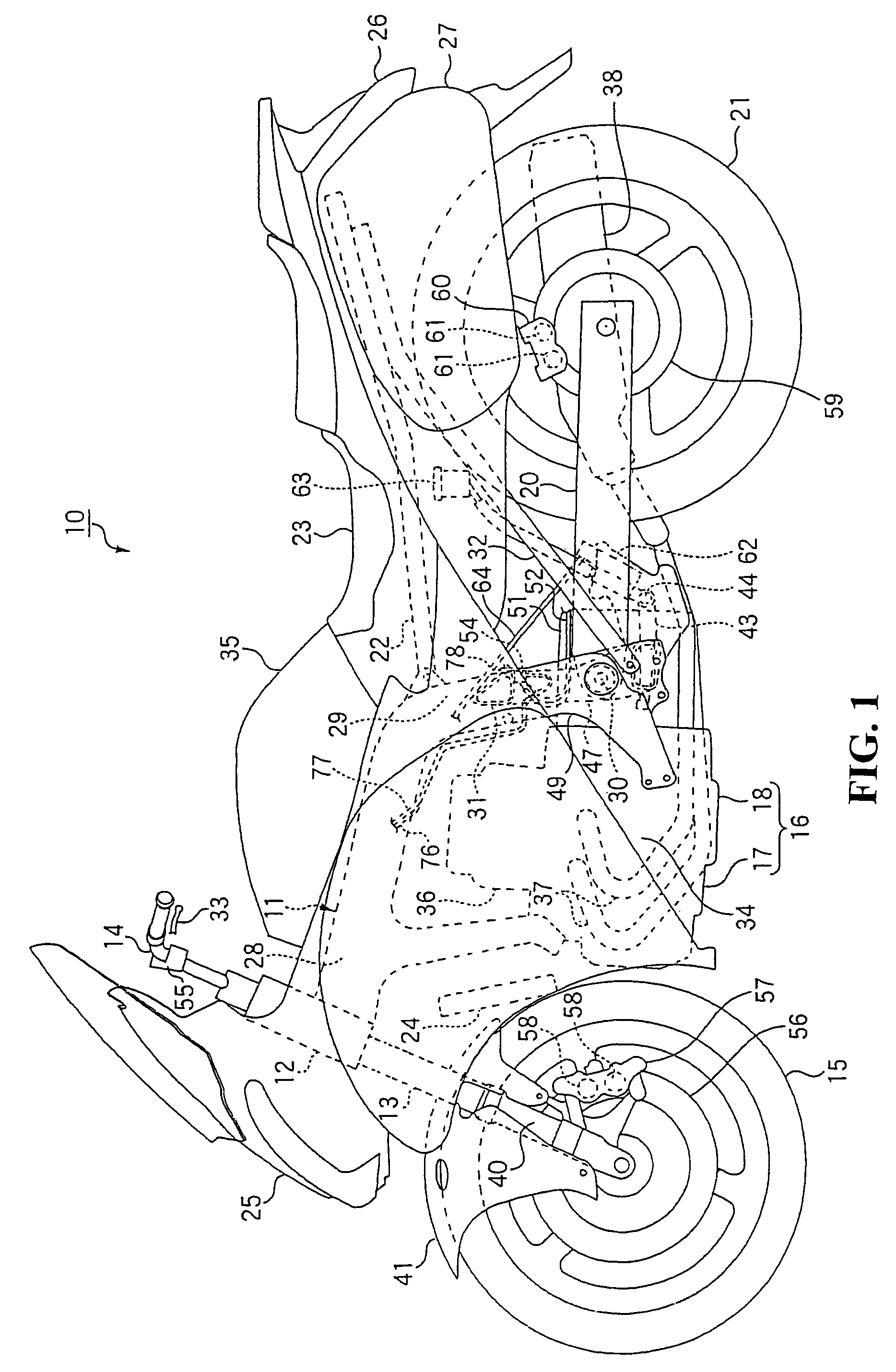
[0027]FIGS. 1 through 6 show an embodiment of the present invention. In the description, the terms “front,”“rear,”“right,” and “left” refer to directions as viewed from the rider on the two-wheeled motor vehicle.

[0028]As shown in FIGS. 1, 2, and 3, the two-wheeled motor vehicle 10 mainly includes a vehicle frame 11 with a front fork 13 attached to a head pipe 12 on a front end of the vehicle frame 11 and a handle 14 coupled to an upper portion of the front fork 13. A front wheel 15 is rotatably mounted on a lower portion of the front fork 13. A power unit 16 including an engine 17 is mounted on a front lower portion of the vehicle frame 11 with a transmission 18, a drive shaft B, and gears in a final drive gear case 39. A swing arm 20 is mounted on a rear lower portion of the vehicle frame 11 for housing the drive shaft B there...


PUM


Abstract

A brake support structure for effectively utilizes a space is disposed so as to be hardly visible in appearance. In addition, the brake support structure protects the pipes. A brake support structure includes a vehicle frame having rear frames extending from main frames with a swing arm having a front end pivotally supported on the rear frames and a rear end for rotatably supporting a rear wheel. Brake pipes are connected to a brake caliper for braking the rear wheel. An upper cross member interconnects the rear frames and is disposed near the swing arm. The brake pipes extend between the upper cross member and the swing arm.

Description

CROSS-REFERENCE TO RELATED APPLICATIONS[0001]The present application claims priority under 35 USC 119 to Japanese Patent Application No. 2006-048899 filed on Feb. 24, 2006 the entire contents of which are hereby incorporated by reference.BACKGROUND OF THE INVENTION[0002]1. Field of the Invention[0003]The present invention relates to a brake support structure for braking wheels of a two-wheeled vehicle. More particularly, to a brake support structure for supporting a brake pipe for supplying a brake fluid.[0004]2. Description of Background Art[0005]A brake support structure is known in related art wherein a rear brake pipe extends from a rear brake caliper and is disposed on an upper surface of a swing arm that turns 180 degrees around over a pivot shaft and is coupled to a rear brake master cylinder. See, for example, Japanese Patent Laid-open No. Hei 7-144676.[0006]However, Japanese Patent Laid-open No. Hei 7-144676 suffers the following two problems:[0007]The first problem relates...

Claims


Application Information

Patent Timeline
Patent Type & Authority Patents(United States)
IPC IPC(8): B62K25/08B60T8/32B60T17/04B62K19/38
CPCB60T17/046B62K25/283B62K19/38
Inventor TOYODA, HIDETOSHI
Owner HONDA MOTOR CO LTD
Learn More