Sheet Feeder

a feeder and front surface technology, applied in the field of feeders, can solve the problems of difficult to reduce the occupied space at the front surface side of the feeder, and achieve the effect of not reducing the work area on the desk, but small spa

Active Publication Date: 2010-05-04
BROTHER KOGYO KK
View PDF12 Cites 14 Cited by
  • Summary
  • Abstract
  • Description
  • Claims
  • Application Information

AI Technical Summary

Benefits of technology

[0018]Therefore, the sheet feeder of the invention can occupy the smaller space so as not to reduce the work area on the desk or the like.

Problems solved by technology

However, in the above described conventional sheet feeder, it has been difficult to make the occupied space smaller at the front surface side of the sheet feeder because the sheet feed cassette must be drawn by the length more than the length of sheets in the depth direction when the sheets of paper are loaded in the sheet feed cassette.

Method used


Image

  • Sheet Feeder
  • Sheet Feeder
  • Sheet Feeder

Examples


embodiment 1

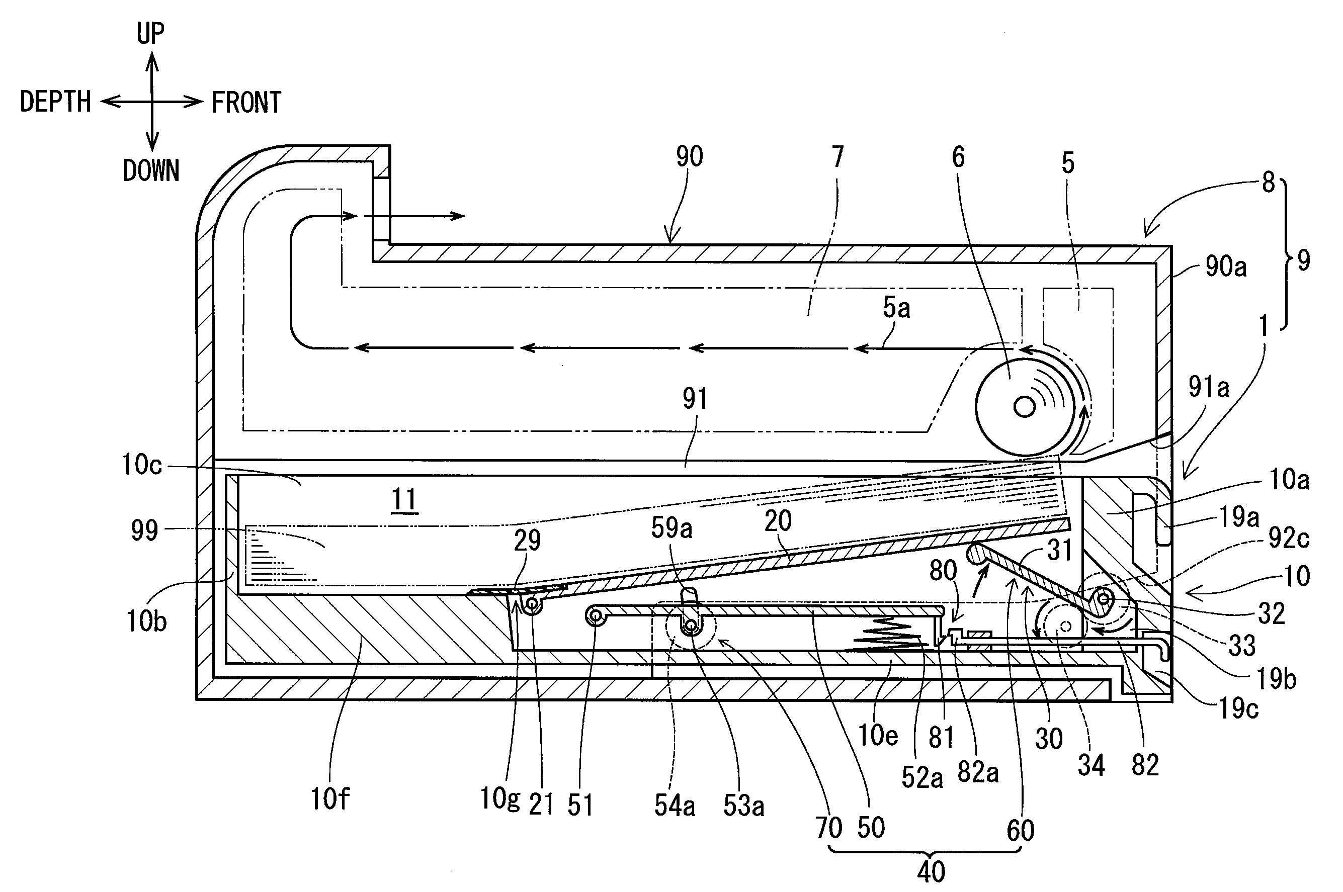
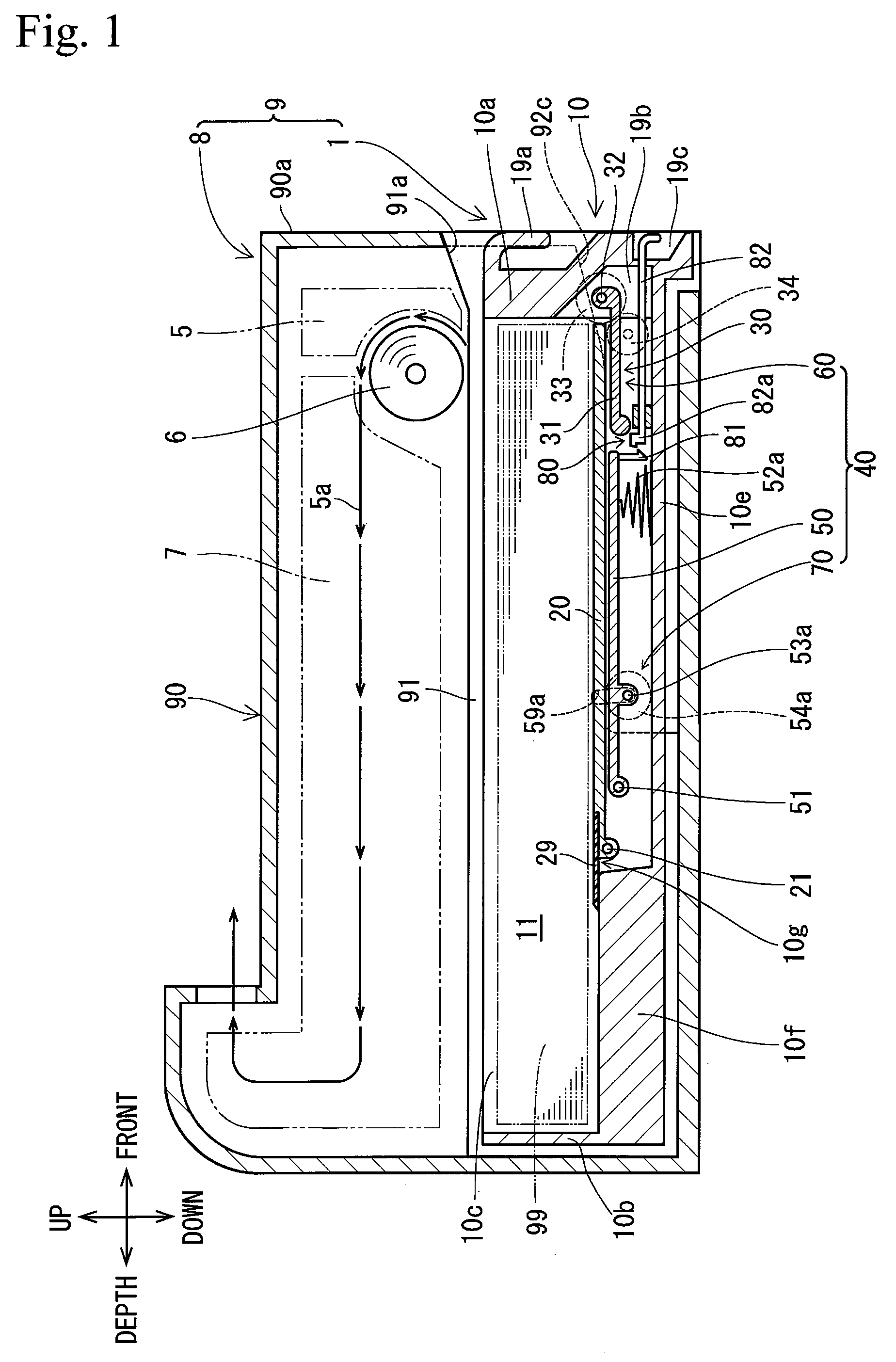
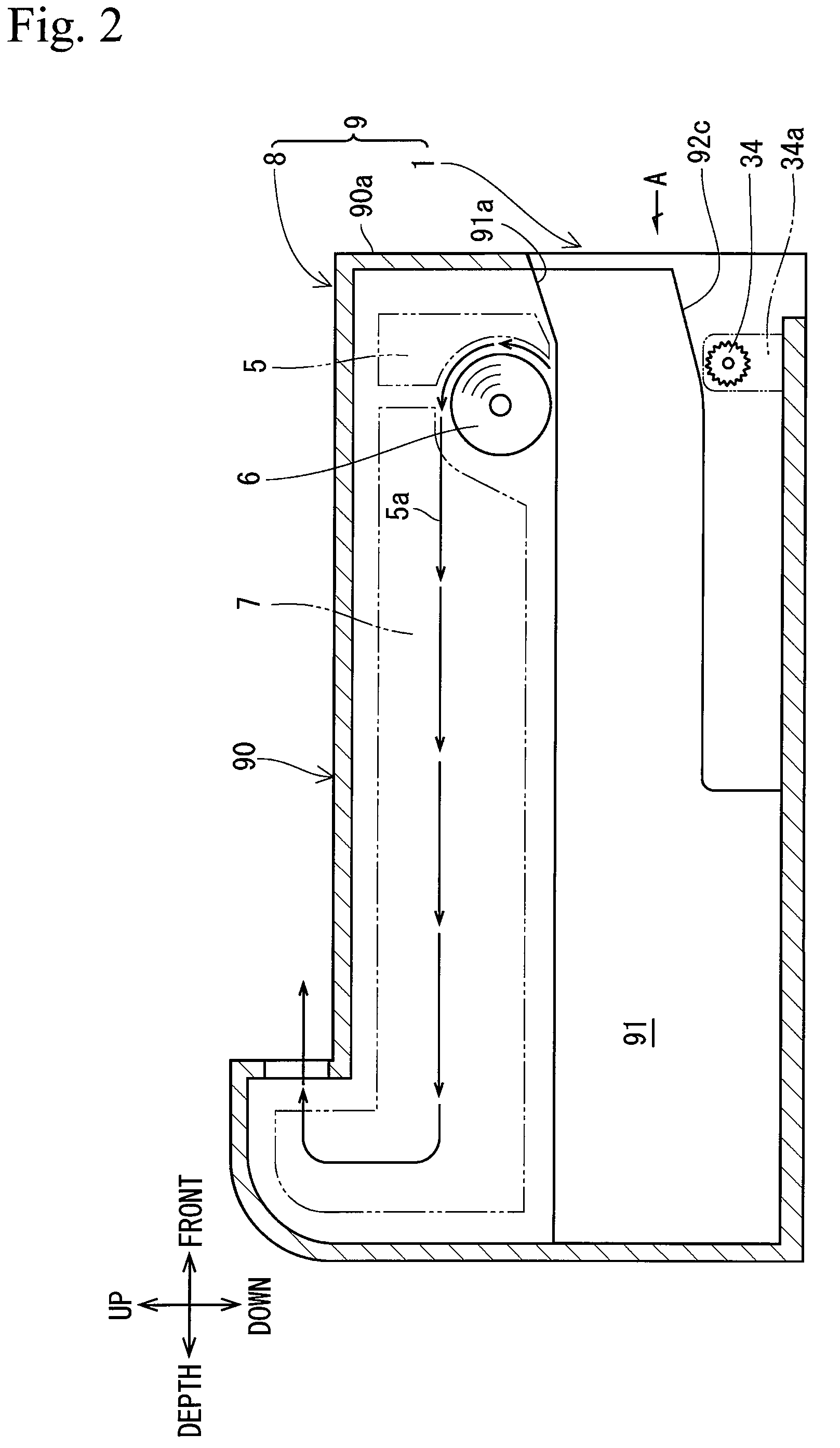
[0037]As shown in FIGS. 1 to 3, a sheet feeder 1 of embodiment 1 configures a printer 9 as an image forming apparatus together with a printer main body 8.

[0038]The printer main body 8 includes a housing 90 having a substantially rectangular parallelepiped shape, and an image forming unit 7 provided in the upper part within the housing 90. The image forming unit 7, though details of which are not shown, adopts a general image forming system including electrophotographic, thermal, inkjet, or other systems.

[0039]The sheet feeder 1 includes the housing 90 in common use with the printer main body 8, a sheet feed cassette 10, a pressure plate 20, a pressure mechanism 30, and a pressure plate regulation mechanism 40.

[0040]The housing 90 has a cassette housing part 91. The cassette housing part 91 is located below the image forming unit 7 and recessed horizontally from the front surface 90a of the housing 90 toward the depth direction. Further, a pick-up roller 6 that is driven rotationally...

embodiment 2

[0074]As shown in FIGS. 12 to 14, a sheet feeder 2 of embodiment 2 includes a sheet width regulation mechanism 100 provided on the bottom surface of the holding chamber 11 (on the upper surface of the front bottom part 10e) of the sheet feeder 1 of embodiment 1, a depth direction regulating plate 102 provided on the upper surface of the depth bottom part 10f, a pressure plate 20a having a T-shape, and a supporting member 50a having a “rectangular frame” shape. The other configuration is the same as that of the sheet feeder 1 of embodiment 1, and the description thereof will omitted.

[0075]The sheet width regulation mechanism 100 has a pair of width direction regulating plates 101a, 101b. The width direction regulating plates 101a, 101b are disposed to face each other at both sides on the upper surface of the front bottom part 10e in the width direction, and slidable in the width direction by a general sliding mechanism or the like (not shown).

[0076]The pressure plate 20a has a front ...

embodiment 3

[0083]As shown in FIGS. 15 to 17, a sheet feeder 3 of embodiment 3 includes a sheet width regulation mechanism 110 provided on the upper surface of a pressure plate 20b having substantially the same shape as that of the pressure plate 20 of the sheet feeder 1 of embodiment 1, and a depth direction regulating plate 102 provided on the upper surface of the depth bottom part 10f. The other configuration is the same as that of the sheet feeder 1 of embodiment 1, and the description thereof will omitted.

[0084]The sheet width regulation mechanism 110 has a pair of width direction regulating plates 111a, 111b. The width direction regulating plates 111a, 111b are disposed to face each other at both sides on the upper surface of the pressure plate 20b in the width direction, and slidable in the width direction by a general sliding mechanism or the like (not shown) provided at the lower surface side of the pressure plate 20b.

[0085]The configuration of the depth direction regulating plate 102...


PUM


Abstract

A sheet feeder includes a housing having a cassette housing part recessed horizontally from the front surface toward the depth direction and a sheet feed cassette that can be drawn from the cassette housing part. The sheet feed cassette has an open top for storing sheets of paper. The sheet feeder includes a pressure plate provided pivotably about a first pivot so as to be inclined downwardly toward the depth direction of the sheet feed cassette and a pressure mechanism that presses sheets of paper against a pick-up roller when the sheet feed cassette is pushed into the cassette housing part. The sheet feeder includes a pressure plate regulation mechanism that inclines the pressure plate downwardly toward the depth direction while separating sheets of paper on the pressure plate or the pressure plate from the pick-up roller when the sheet feed cassette is drawn from the cassette housing part.

Description

CROSS-REFERENCE TO RELATED APPLICATION[0001]This application claims the benefit of Japanese Patent Application No. 2006-228623 filed on Aug. 25, 2006, which is incorporated herein by reference.BACKGROUND OF THE INVENTION[0002]The present invention relates to a sheet feeder.[0003]Conventional sheet feeders are disclosed in JP-A-2005-292236 and JP-A-2006-176321. The sheet feeder has a housing, a sheet feed cassette, a pressure plate, and a pressure mechanism.[0004]The housing has a cassette housing part. The cassette housing part is recessed horizontally from the front surface toward the depth direction. Further, a pick-up roller that is driven rotationally about a horizontal axis perpendicular to the depth direction is provided in the upper part at the front surface side within an opening of the cassette housing part.[0005]The sheet feed cassette has a holding chamber having an open top for storing stacked sheets of paper, and can be housed within the cassette housing part and drawn ...

Claims


Application Information

Patent Timeline
Patent Type & Authority Patents(United States)
IPC IPC(8): B65H3/06
CPCB65H1/26G03G15/6511B65H2403/50B65H2405/1117B65H2405/32G03G2221/1672G03G2215/00396B65H2220/09B65H1/266
Inventor KUSAMA, TAKURO
Owner BROTHER KOGYO KK
Why Eureka
Try Eureka