Collision barrier device for projecting loads

a technology of collision barrier and projecting load, which is applied in the direction of roadway safety arrangements, roads, construction, etc., can solve the problems of exposing the occupants to extraordinary risk of severe injury or death, and never allowing the current automobile safety system to mitigate the impact, so as to increase the likelihood

Inactive Publication Date: 2010-05-04
OMNITEK PARTNERS LLC
View PDF7 Cites 5 Cited by
  • Summary
  • Abstract
  • Description
  • Claims
  • Application Information

AI Technical Summary

Benefits of technology

[0026]Further yet provided is a method for attenuating an impact of a first vehicle on a second vehicle carrying a projecting load. The method comprising: fastening a body portion having at least an impact portion to an end portion of the projecting load; and configuring at least a portion of the impact portion and the fastening portion such that the impact portion is nearer to a surface traveled on by the vehicle than the fastening portion so as to lower a point of the impact towards a surface traveled on the first and second vehicles.
[0027]The method can further comprise providing the impact portion with a surface area greater than a surface area of the end portion of the projecting load so as to increase a likelihood that an operator of the first vehicle will be aware of a proximity to the projecting load.

Problems solved by technology

There exists, however, a common and necessary highway transport practice which, if involved in a collision, never allows for any current automobile safety system to mitigate the impact.
This practice may result from the need to transport loads, sometimes exceeding 100′ in length, on roads and highways while maintaining a relatively short vehicle wheelbase for maneuverability.
In either case, the projected load presents a grave danger to other vehicles, especially automobiles, because of two intrinsic geometric parameters of the projecting load.
If a passenger vehicle collides with a projecting load, the end of the projecting load will pierce the windshield of the automobile, exposing the occupants to extraordinary risk of severe injury or death.
This, combined with the typical mass, rigidity, and secure attachment of projected loads (utility poles, bridge trusses, I-beams, etc) when compared to the strength of the upper portion of a passenger vehicle, results in the immediate deformation and failure of the passenger vehicle components (windshield, roof, etc.) and exposure of the passengers to the risk of severe injury or death in any collision of appreciable magnitude.

Method used


Image

  • Collision barrier device for projecting loads
  • Collision barrier device for projecting loads
  • Collision barrier device for projecting loads

Examples


Embodiment Construction

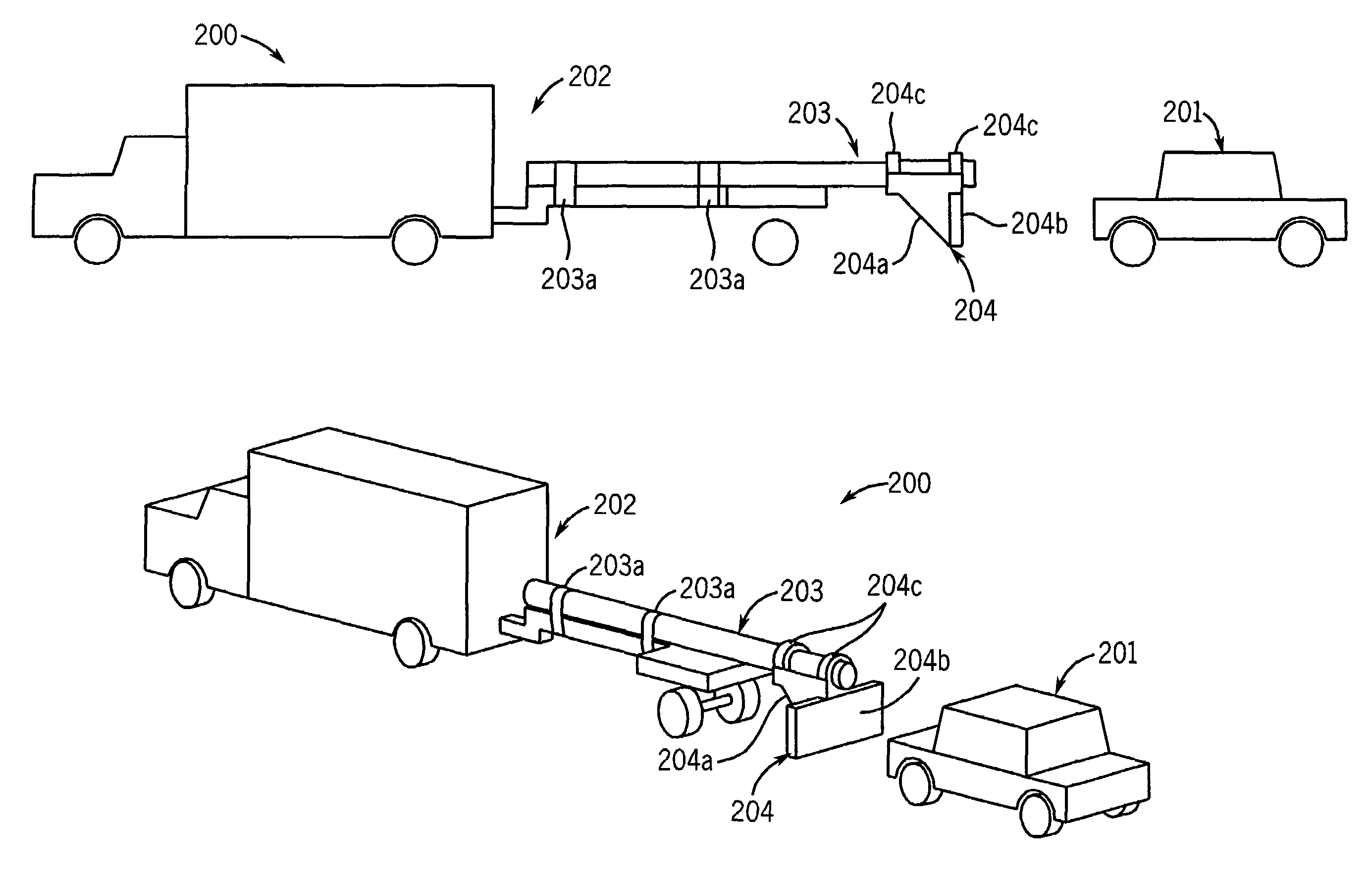
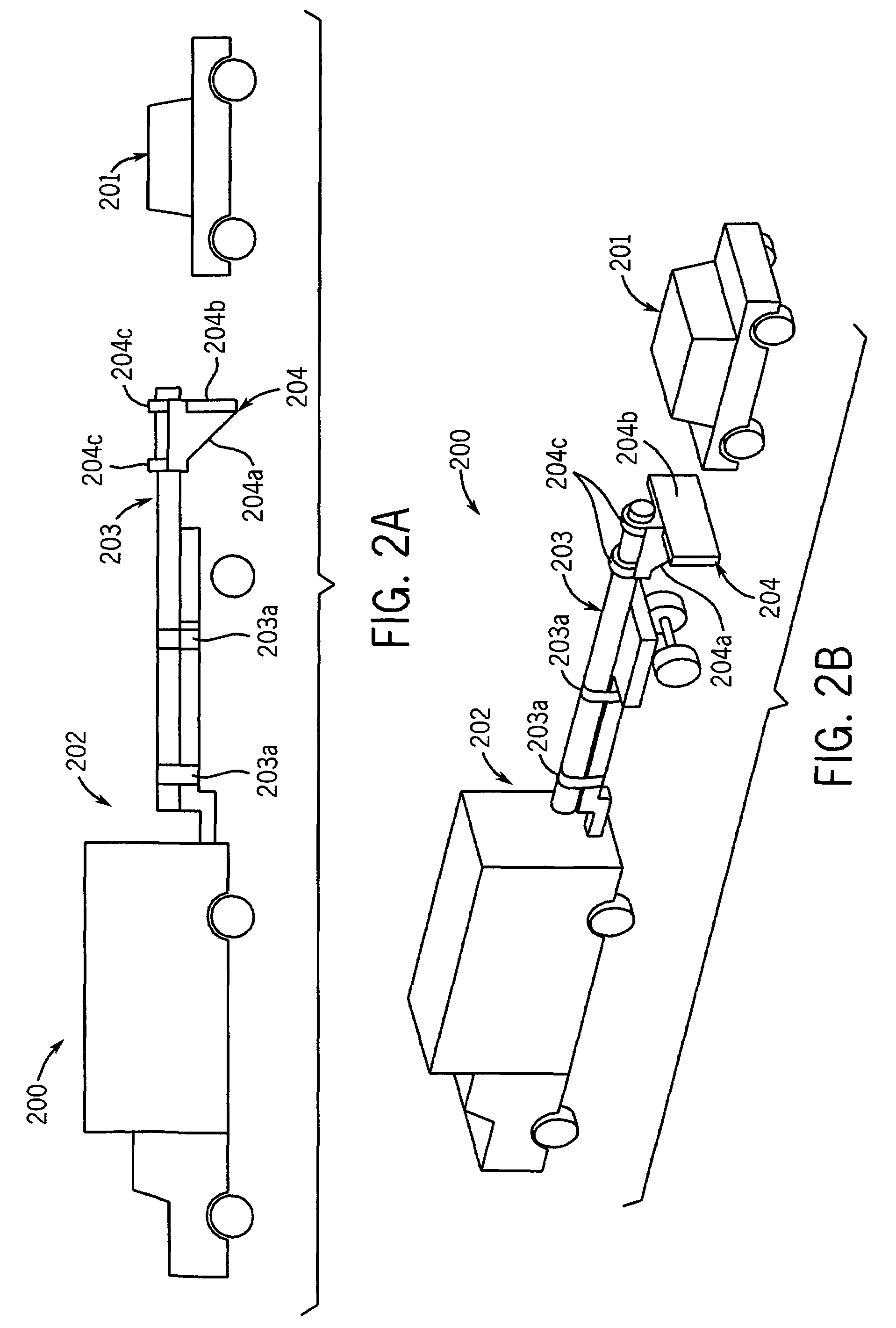
[0044]Although this invention is applicable to attenuating any impact between two objects whose intended impact points are misaligned, it is particularly useful in mitigating rear-end collisions between passenger vehicles or light trucks and projecting loads carried by commercial vehicles. Therefore, without limiting the applicability of the present invention to mitigation of rear-end collisions between passenger vehicles or light trucks and projecting loads carried by commercial vehicles, it will be described in such an environment.

[0045]Furthermore, although this invention is applicable to numerous and various types of projecting loads, it has been found particularly useful in the environment of utility poles. Therefore, without limiting the applicability of the invention to utility poles, the invention will be described in such environment.

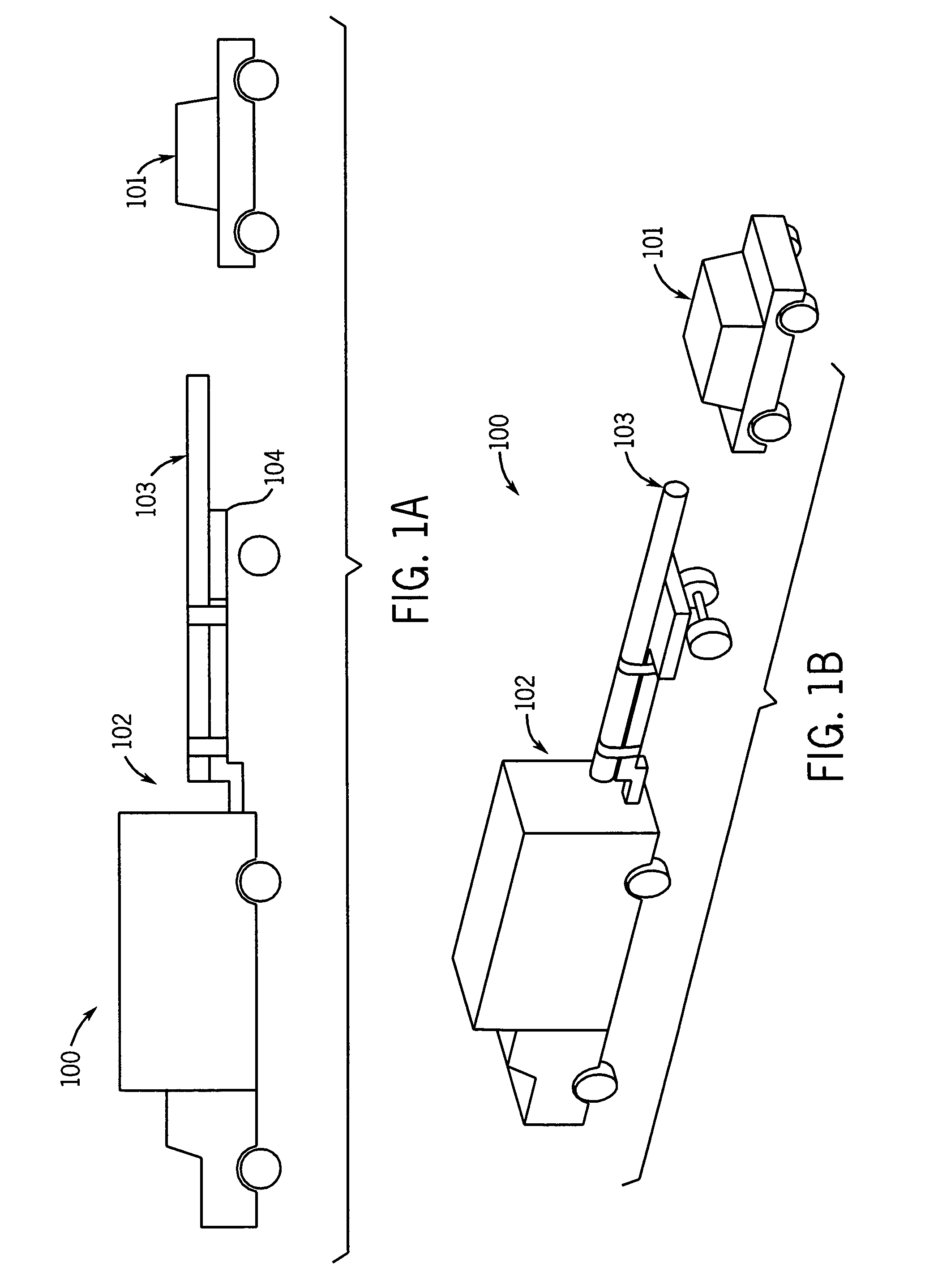
[0046]Referring now to FIGS. 1a and 1b, there is illustrated a collision interaction schematic of the prior art generally referred to by refer...


PUM


Abstract

A crash barrier device including: a body portion having at least an impact portion; and a fastening portion configured to fasten the body portion to a projecting load being carried by a vehicle; wherein the impact portion and fastening portion are configured such that the impact portion is nearer to a surface traveled on by the vehicle than the fastening portion. A system for carrying projecting loads is also provided and includes: a trailer having wheels and fastener(s) for fastening the trailer to a powered vehicle; and the crash barrier device.

Description

CROSS-REFERENCE TO RELATED APPLICATION[0001]This application claims the benefit of provisional application Ser. No. 60 / 859,191 filed on Nov. 15, 2006, the contents of which is incorporated herein by reference.BACKGROUND[0002]1. Field of the Invention[0003]The present invention relates generally to automotive collision avoidance, and mitigation or attenuation, and more specifically to avoiding or mitigating vehicle collisions between cargo carried as a projecting load and any other vehicle.[0004]2. Prior Art[0005]The basis of providing vehicle bumpers is to provide a durable collision interface with relatively large surface area to transmit the collision force to the vehicle chassis regardless of the point of impact or the distribution of collision forces. Once transmitted to the chassis, the impact forces are transmitted to the vehicle occupants via safety belts and / or air bags. This widely employed method works to lessen the effects of highly concentrated impacts, such as those wit...

Claims


Application Information

Patent Timeline
Patent Type & Authority Patents(United States)
IPC IPC(8): B60R19/26
CPCB60R19/00B60R2019/005
Inventor MURRAY, RICHARDSPINELLI, THOMAS
Owner OMNITEK PARTNERS LLC
Why Eureka
Try Eureka