Electric power source

a technology of electric power source and battery module, which is applied in the field of electric power source, can solve the problems of generating a higher temperature, difficult or impossible to uniformly cool all battery modules, and reducing performance efficiency, so as to reduce temperature difference, reduce pressure loss, and increase temperature difference

Inactive Publication Date: 2010-05-04
SANYO ELECTRIC CO LTD
View PDF6 Cites 6 Cited by
  • Summary
  • Abstract
  • Description
  • Claims
  • Application Information

AI Technical Summary

Benefits of technology

[0010]Japanese Laid-Open Patent Application No. 1999-329518, on the other hand, describes a power source which contains battery modules in three or more tiers within a holder case. In that power source, a plurality of battery modules, positioned in a parallel relationship relative to one another and separated along the blowing direction of cooling air, are contained within the holder case in a multi-tier manner. This power source allows the battery modules to be cooled by forcibly blowing the cooling air in between the battery modules. Disadvantageously, however, such a cooling structure is prone to make a cooling performance less efficient for a battery module in the downstream than for battery module in the upstream, thus generating a higher temperature. To overcome such a shortcoming, the holder case has an air turbulence accelerator, such as a dummy battery unit, provided in the uppermost stream so that a stream of cooling air coming into the holder case may be disturbed for allowing the battery module in the upstream to be effectively cooled. Also, the holder case has an auxiliary air intake, provided intermediate in a path of the cooling air, for allowing the cooling air in, and thus a cooling effectiveness is enhanced for a battery in the downstream.
[0011]In the above-described power source, a cooling effect for the battery module in the downstream can certainly be enhanced by means of the air turbulence or by the cooling air which is taken in intermediately. With such structure, however, it is impossible to cool all battery modules down to a uniform temperature.
[0014]The above-described power source carries the advantage that the batteries are contained within the holder case in a multi-tier manner and all such batteries can be cooled uniformly, with a reduced temperature difference. This is made possible because this power source is featured in that: (1) the plurality of batteries are stacked in more than three tiers within the battery case, and the battery case is divided midway into the first and second sub holder cases which contain the batteries in the different numbers of tiers; (2) the intermediary duct is provided between the divided first and second sub holder cases; (3) the outer duct is respectively provided outside each of the holder cases; (4) cooling air is allowed to flow from the intermediary duct through the holder case into the outer duct or alternatively from the outer duct through the holder case into the intermediary duct, for cooling the batteries contained in the holder case; and (5) the second outer duct which is placed outside the second sub holder case containing the batteries in the smaller number of tiers experiences a larger pressure loss than does the first outer duct which is placed outside the first sub holder case containing the batteries in the larger number of tiers. In particular, the inventive power source is so constructed and arranged that the batteries contained in the battery case in a multi-tier manner are divided into the first and second sub holder cases having the different numbers of battery-stacked tiers, and that each individual battery is uniformly cooled by adjusting the pressure losses prevalent in the outer ducts which are provided outside the holder cases having the different numbers of battery-stacked tiers. Since the batteries are not contained in the same number of tiers in the first and second sub holder cases, the power source thus structured is not limited to the even number of battery-stacked tiers in each of the battery case. For example, to cool the batteries, a power source containing batteries in total five tiers can have the batteries divided into three and two tiers in the holder cases; a power source containing batteries in total six tiers can have the batteries divided into two and four tiers in the holder cases; and a power source containing batteries in total seven tiers can have the batteries divided into four and three tiers in the holder cases. In addition, while a conventional type of power source has suffered difficulties of uniformly cooling the batteries contained in holder cases which have the different numbers of battery-stacked tiers, thus resulting in a larger temperature difference among the batteries, the inventive power source allows the batteries contained in both of the holder cases to be uniformly cooled by adjusting the pressure losses prevalent in the outer ducts placed outside the holder cases. As such, while the battery case is divided into holder cases having the different numbers of battery-stacked tiers, the batteries contained in both of the holder cases can be uniformly cooled, with a reduced temperature difference.
[0015]For example, in the power source described in an embodiment of the present invention, batteries are contained in three tiers in the first sub holder case and in two tiers in the second sub holder case. The present power source is so constructed and arranged that the ratio of the first outer duct to the second outer duct is 3:2 by inside width, whereby a pressure loss is increased in the second outer duct due to a smaller inside width. This unique structure serves to improve a maximum temperature deviation among the batteries by 40% as compared with a conventional type of power source in which both of the outer ducts experience the same pressure loss, and the above-described design for the present power source has successfully facilitated cooling all the batteries uniformly, with a reduced temperature difference. Since the battery case is divided midway to be provided with the intermediary duct and allows the cooling air to be blown separately into the upper and lower holder cases from the intermediary duct, the inventive power source has also made it possible to effectively cool all the batteries and to advantageously obtain a considerably reduced battery temperature, as compared with a conventional type of power source that contains batteries in unseparated five tiers.

Problems solved by technology

However, when battery modules are to be contained in three or more tiers within the holder case for reducing a total installation area, it becomes difficult or impossible to uniformly cool all the battery modules.
Disadvantageously, however, such a cooling structure is prone to make a cooling performance less efficient for a battery module in the downstream than for battery module in the upstream, thus generating a higher temperature.
With such structure, however, it is impossible to cool all battery modules down to a uniform temperature.

Method used


Image

  • Electric power source
  • Electric power source
  • Electric power source

Examples


Embodiment Construction

)

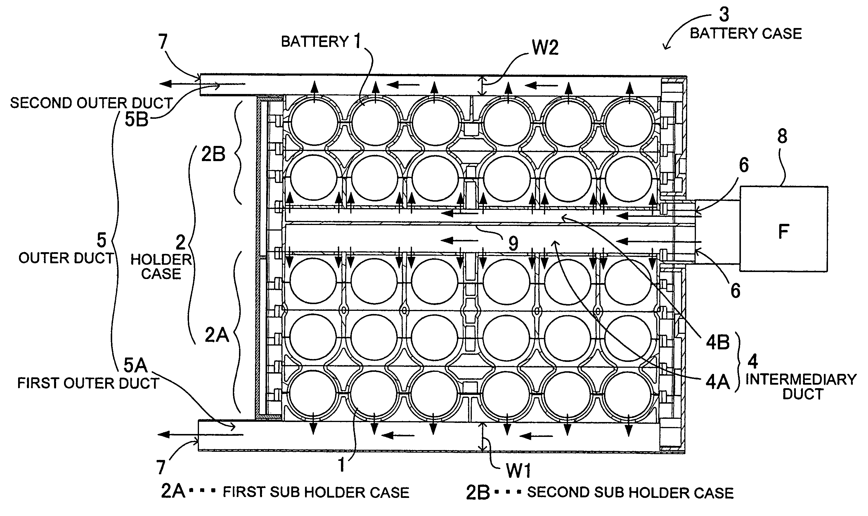
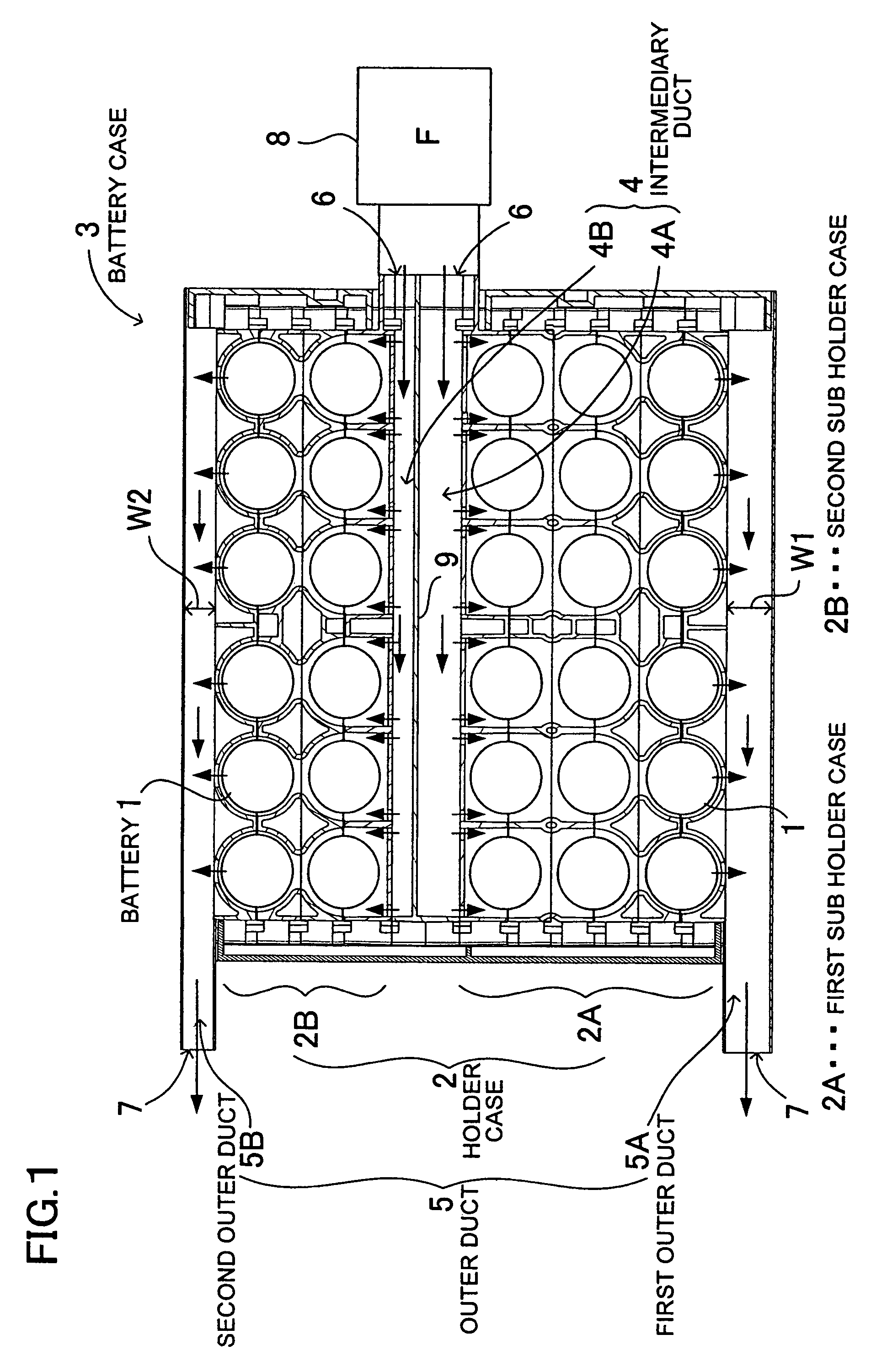
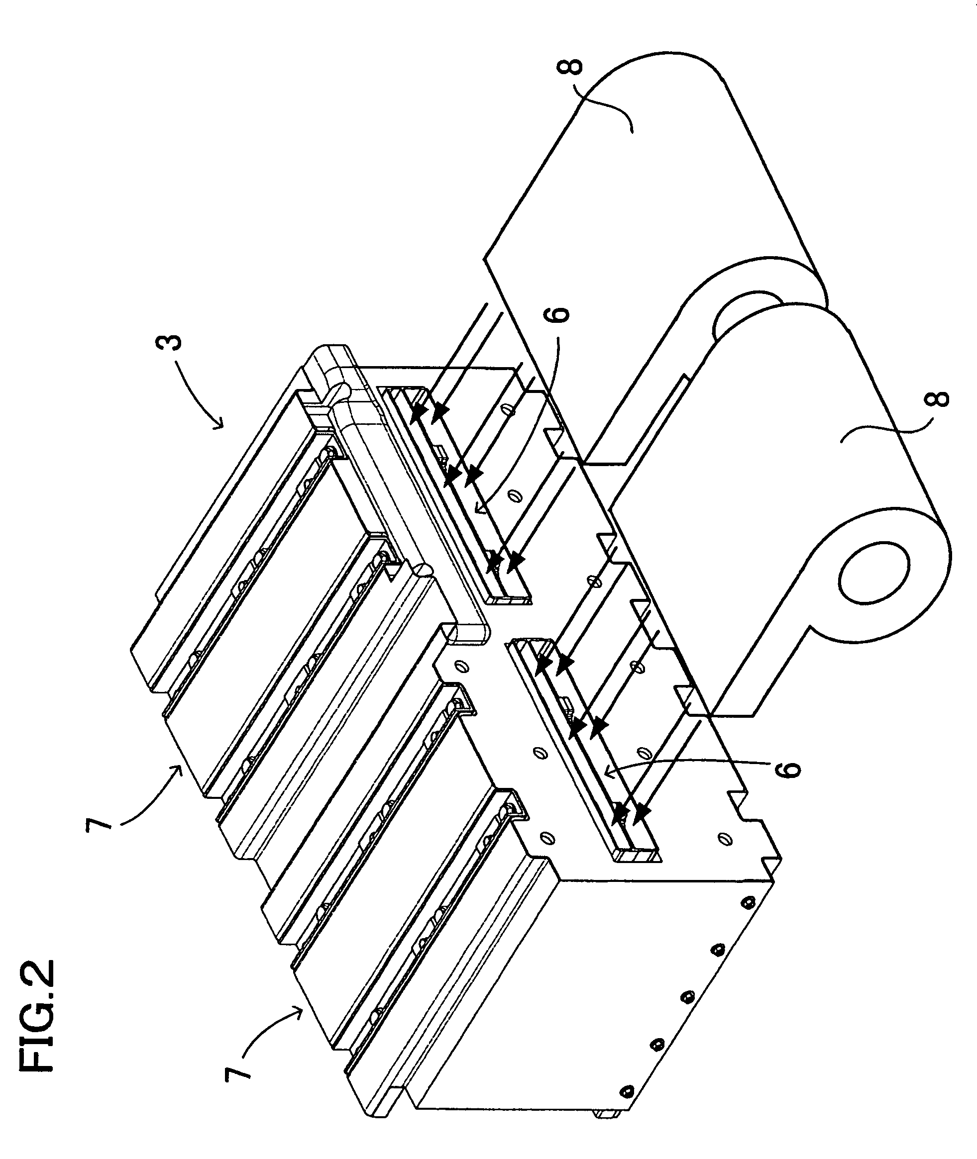
[0031]The electric power source, shown in the cross-sectional view in FIG. 1 and the perspective view in FIG. 2, contains a plurality of batteries 1 stacked in five tiers within the battery case 3. Although the illustrated power source contains the batteries 1 in five tiers, the inventive power source may contain batteries in seven or more tiers as well. The battery case 3 is divided into a first sub holder case 2A and a second sub holder case 2B midway of the direction of stacking the batteries 1, namely, midway between upper and lower stages as viewed in the Figure. In the illustrated battery case 3, the first sub holder case 2A is disposed in the lower stage and the second sub holder case 2B is disposed in the upper stage. Being thus divided, the first sub holder case 2A contains the batteries 1 in the greater number of tiers than does the second sub holder case 2B. In the illustrated battery case 3, the batteries 1 are contained in three tiers within the first sub holder case 2...


PUM

PropertyMeasurementUnit
electric poweraaaaaaaaaa
pressure lossaaaaaaaaaa
widthaaaaaaaaaa

Abstract

The power source contains a plurality of batteries stacked in more than three tiers within a battery case divided into a first sub holder case and second sub holder case, and the first sub holder case contains the batteries in a larger number of tiers than the second sub holder case. An intermediary duct is provided between the two sub holder cases, and a first outer duct and a second outer duct are respectively provided outside each of the two sub holder cases. The batteries in the holder case are cooled by the cooling air which flows from the intermediary duct through the holder case into the outer duct for exhaustion. Further, the second outer duct is designed to experience a larger pressure loss than the first outer duct.

Description

BACKGROUND OF THE INVENTION[0001]1. Field of the Invention[0002]The present invention relates generally to an electric power source which contains a plurality of batteries in its battery case and pertains specifically to a power source which is used to supply a power to a motor mainly for driving a vehicle.[0003]2. Description of the Related Art[0004]An electric motor vehicle, such as an electric car and a hybrid car which is designed to travel optionally with an internal combustion engine or with an electric motor, uses an electric power source, having a multitude of batteries interconnected, as a power unit for supplying electric power to a drive motor.[0005]An electric power source used for this kind of application is designed to provide a high output voltage so that a large amount electricity may be supplied to a motor which requires a high power. In order to satisfy such a design need, a multitude of batteries, interconnected in series, are contained in a holder case. For examp...

Claims


Application Information

Patent Timeline
Patent Type & Authority Patents(United States)
IPC IPC(8): H01M10/50H01M6/42H01M10/60H01M10/613H01M10/617H01M10/625H01M10/643H01M10/651H01M10/6556H01M10/6563H01M50/213H01M50/291
CPCH01M2/1077H01M10/5004H01M10/5073H01M10/5036H01M10/5038H01M10/5067H01M2/105H01M10/5016H01M10/503H01M10/625H01M10/6563H01M10/652H01M10/643H01M10/6566H01M10/651H01M10/613Y02E60/10H01M50/213H01M50/291
Inventor SHIMIZU, HIDEO
Owner SANYO ELECTRIC CO LTD
Why Eureka
Try Eureka