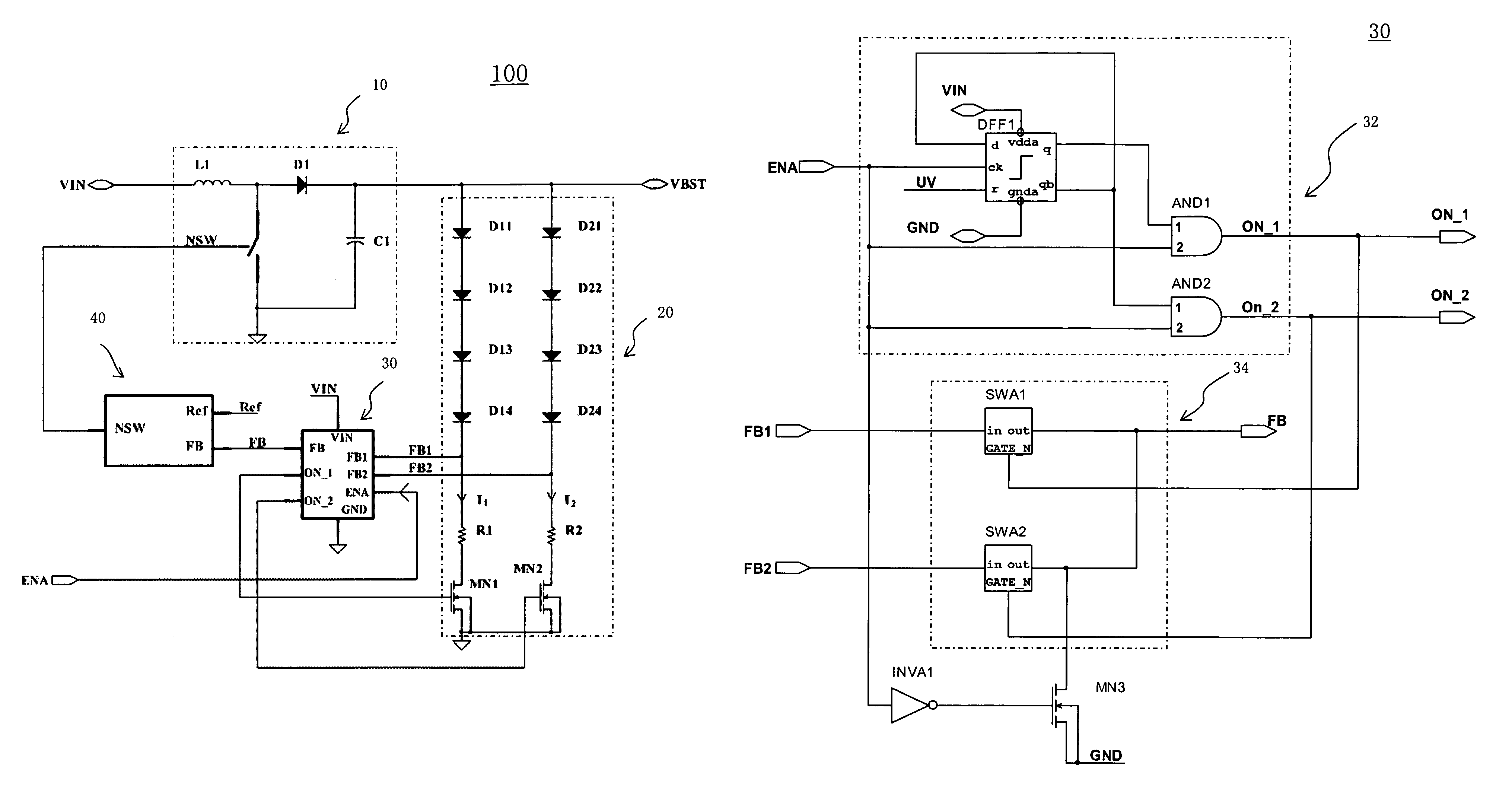
Driver and method for driving LEDS on multiple branch circuits
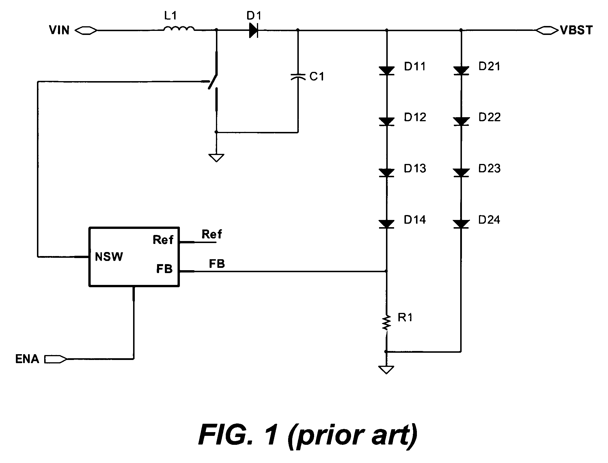
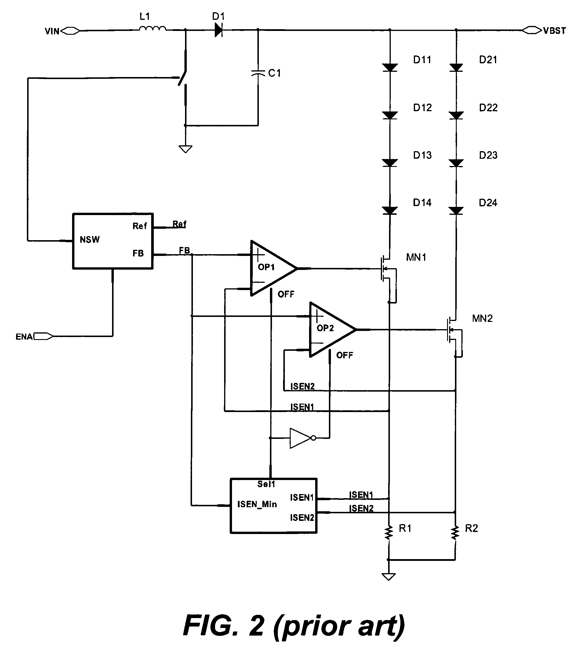
a technology of leds and circuits, applied in the direction of electric variable regulation, process and machine control, instruments, etc., can solve the problems of consuming additional power, serious current mismatch between wled branches, and not being able to drive leds on multiple branches
- Summary
- Abstract
- Description
- Claims
- Application Information
AI Technical Summary
Benefits of technology
Problems solved by technology
Method used
Image

Examples
Embodiment Construction
[0020]The detailed description of the present invention is presented largely in terms of procedures, steps, logic blocks, processing, or other symbolic representations that directly or indirectly resemble the operations of devices or systems contemplated in the present invention. These descriptions and representations are typically used by those skilled in the art to most effectively convey the substance of their work to others skilled in the art.
[0021]Reference herein to “one embodiment” or “an embodiment” means that a particular feature, structure, or characteristic described in connection with the embodiment can be included in at least one embodiment of the invention. The appearances of the phrase “in one embodiment” in various places in the specification are not necessarily all referring to the same embodiment, nor are separate or alternative embodiments mutually exclusive of other embodiments. Further, the order of blocks in process flowcharts or diagrams or the use of sequence...
PUM
 Abstract
Description
Claims
Application Information
PatSnap Eureka turns technology decisions into work you can execute. Powered by our Innovation Knowledge Graph, it runs expert workflows across engineering, life sciences, materials and intellectual property. Get your review-ready output in minutes.


