Extensible object location system and method using multiple references

a technology of object location and reference, applied in the direction of direction finders, direction finders using radio waves, instruments, etc., can solve the problems of object location not being determined, clock frequency degraded position measurement accuracy, signal dispersion in the cable,

Active Publication Date: 2010-05-04
ZEBRA TECH CORP
View PDF17 Cites 82 Cited by
  • Summary
  • Abstract
  • Description
  • Claims
  • Application Information

AI Technical Summary

Problems solved by technology

One drawback of this approach was signal dispersion in the cable.
However, a drawback of this approach relates to the fact that these systems are plesiochronous, or “nearly” synchronous; i.e., timing reference signals were arbitrarily close in frequency (within some specified limits), but were not sourced from the same clock signal.
As each monitoring station had an independent clock source, small differences in clock frequencies degraded accuracy in position measurement, which worsened over time.
While this was suitable for frequency synchronization in benign outdoor conditions, monitoring stations operating indoors or in urban environments could not generally rely upon receiving a GPS timing signal, and consequently, object location could not be determined.
However, a drawback was the lack of a provision to reset the counters or otherwise control the relative phase between them.
Non-compensated phase offset between counters degraded position accuracy.
A drawback of this approach was that, upon receiving a first tag transmission, the system was temporarily “disarmed” and thus unable to process a second tag transmission until the network completed the transfer of measurement data.
Thus, it was possible that one or more tag transmissions were lost in the process.
Thus, one drawback of this approach was that each monitoring station had to be equipped with two distinct RF receivers—a first to sense the tag transmission and a second to sense the synchronization signal.
Alternatively, the system disclosed by U.S. Pat. No. 3,419,865 included a cable interconnecting a central unit and each monitoring station to enable “adjusting their time clocks to precise mutual synchronization.” A drawback of this approach, however, was signal dispersion in the cable, which reduced pulse sharpness and timing accuracy of the synchronizing signal.
Another problem unique to determining object location or to track assets is that, in order to accurately determine position, a minimum number of receivers at the monitoring stations (i.e. typically three receivers) must have a direct (i.e., a line-of-sight or, at most, an attenuated line-of-sight) transmission path.
However, due to the nature of indoor environments, there may only be a limited number of such direct transmission paths.
For example, walls, machinery, containers, and other materials may create signal attenuation or even complete signal blockage.
Thus, there may exist certain zones within the monitored region in which position accuracy may be degraded for lack of adequate signal reception.
A potential drawback of using an over-determined system relates to the fact that hyperbolic ranging algorithms can calculate more than one mathematically valid position.
That is, ambiguities in position determination can arise.
A drawback of this approach is that it is possible for a signal to have a propagation anomaly and yet not produce an error sufficiently large enough to be rejected or filtered out.
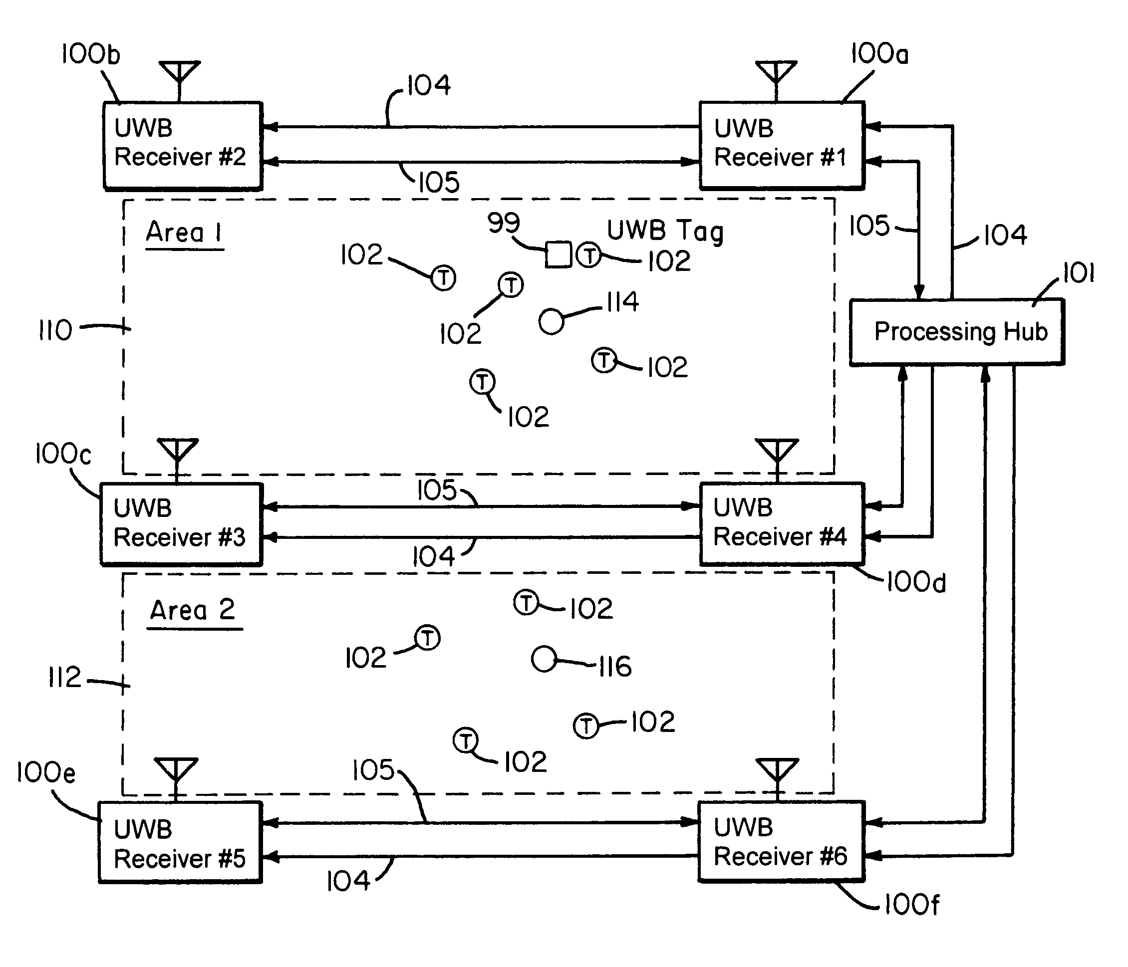
A single-reference tag system, however, had limitations in certain situations.
With a worst case range of 200 feet from reference tag to monitoring station (UWB receiver), a single reference tag system has a maximum coverage area of approximately 40,000 square feet, which may not be adequate for certain applications.
In indoor applications, this can be quite challenging, and sometimes impossible, when obstructions (e.g., steel-reinforced concrete walls, machinery, metal doors, etc.) create significant signal attenuation or even complete signal blockage.
While one solution to such limitations would be to replicate the object location system with a new reference transmitter supplied for each replication, cost constraints ultimately limit the benefit of such a simple approach.
Furthermore, there are numerous implementation geometries (described further below) in which a single reference tag may not be sufficient to overcome signal blockages, resulting in a system with either increased measurement inaccuracies or dead zones in which no positional data can be extracted.

Method used


Image

  • Extensible object location system and method using multiple references
  • Extensible object location system and method using multiple references
  • Extensible object location system and method using multiple references

Examples


example

Signal Blockage Problem

[0067]A limitation of a system using a single reference tag is possible blockage of direct transmission paths between the reference tag and one or more of the receivers. As noted above, a direct transmission path from the reference tag to the receivers must be established in order to generate a full matrix of all timing or counter offsets (ΔRij). However, due to the nature of an indoor environment, there may only be a limited number of such unobstructed, direct transmission paths. For example, walls, machinery, and other obstacles may create signal attenuation or even complete signal blockage from certain tag locations, negating the ability to use a single reference system or method. In FIG. 5, for example, reference tag 201 has direct line-of-sight paths only to three monitoring stations 141, 142, and 144 (i.e., UWB Receivers #1, 2 and 4) while the transmission path to station 143 (Receiver #3) is completely blocked by an RF barrier 300 thereby preventing a s...


PUM


Abstract

An ultra wideband (UWB) or short-pulse RF system is disclosed that can be used to precisely locate or track objects (such as personnel, equipment, assets, etc.) in real-time in an arbitrarily large, physically connected or disconnected, multipath and / or noisy environment. A system implementation includes multiple zones or groups of receivers that receives RF signals transmitted by one or more timing reference tags and one or more objects having associated object tags. Each zone or group may share a common receiver. By combining a multiple reference tag system with a virtual group of receivers, i.e., a zoning technique or system, a cost-effective system can be provided that offers scalability and flexibility to monitor a significantly expanded coverage area.

Description

CROSS-REFERENCE TO RELATED PATENT APPLICATION[0001]This invention claims the benefit under 35 U.S.C. §119(e) of Provisional Application Ser. No. 60 / 679,235 filed May 10, 2005 in the names of the same inventors hereof, entitled “Extensible Object Location System and Method Using Multiple References.”BACKGROUND[0002]This invention relates to a radio frequency (“RF”) object location method and apparatus. More specifically, this invention relates to system architecture, as well as an improved calibration method and apparatus for precisely locating an object(s) in an arbitrarily large, physically connected or disconnected multipath, and / or noisy environment.[0003]RF location systems are used to keep track of objects such as inventory, materiel, equipment, personnel, or other items. In such systems, objects to be located typically have associated transmitters or transponders, commonly referred to as active RF tags. To locate the object, various techniques have previously been used to proc...

Claims


Application Information

Patent Timeline
Patent Type & Authority Patents(United States)
IPC IPC(8): G01S3/02
CPCG01S5/10G01S5/02213G01S5/06G01S5/021
Inventor AMETI, AITANCHEN, KEMINGFONTANA, ROBERT J.RICHLEY, EDWARD A.TURNER, BELINDA
Owner ZEBRA TECH CORP
Why Eureka
Try Eureka