
Imaging apparatus with memory for storing camera through image data

a technology of image data and memory, applied in the field of imaging apparatus, can solve the problems of inability to accurately capture the picture at the expected moment, and the delay in shutter timing cannot be negligible for the camera user

Inactive Publication Date: 2010-05-04
FUJIFILM CORP
View PDF8 Cites 33 Cited by
  • Summary
  • Abstract
  • Description
  • Claims
  • Application Information

AI Technical Summary

Benefits of technology

[0007]In view of the foregoing, a primary object of the present invention is to provide an imaging apparatus that reduces the time lag from shooting an image frame by an image sensor to displaying the image frame as the camera-through image on a display device.
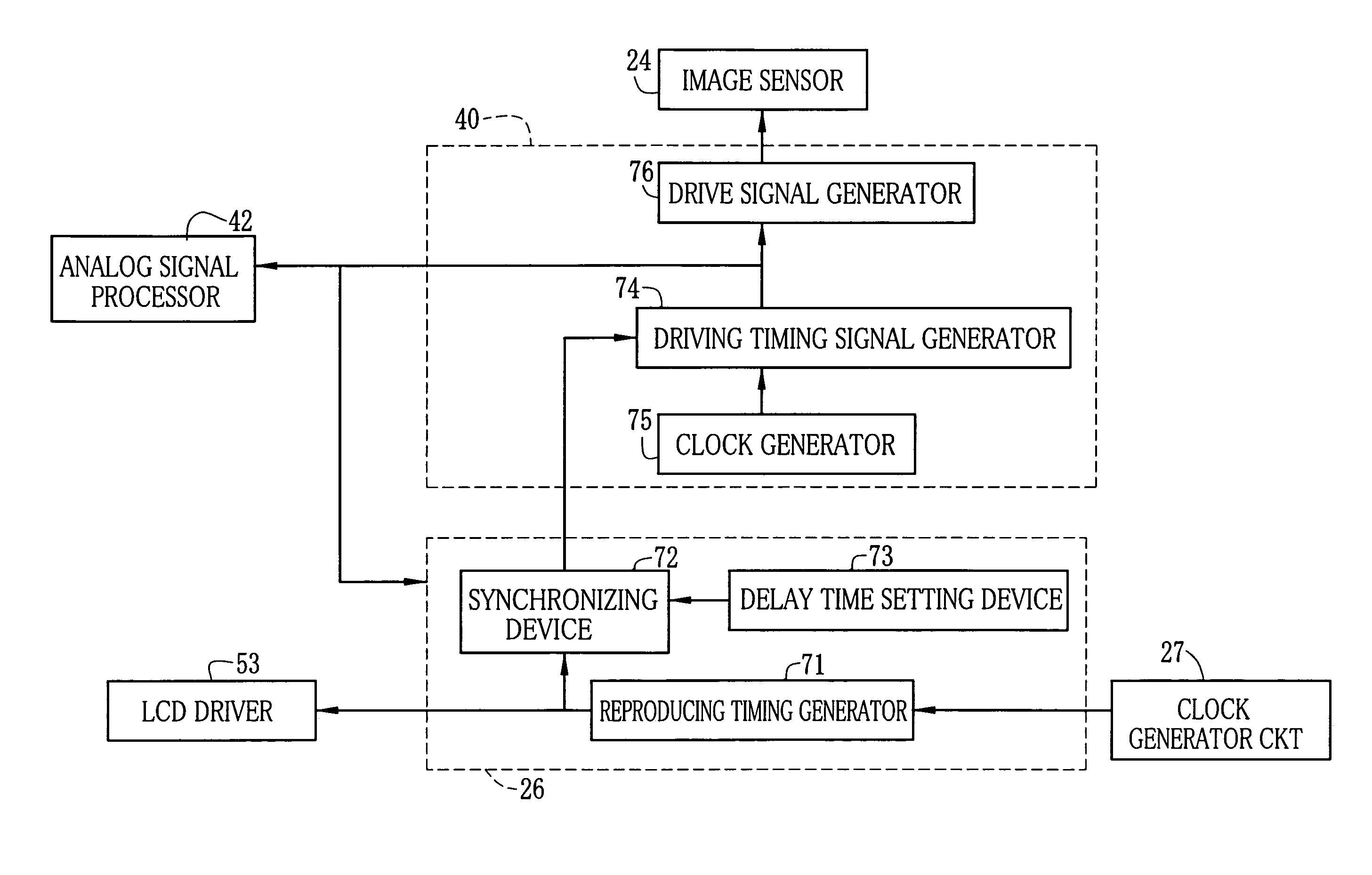
[0013]According to the present invention, the synchronizing device synchronizes the driving timing signal that defines the driving timing of the image sensor with the reproduction timing signal that defines the timing of reading of the image signal from the image memory, while providing such a phase difference between these timing signals that the reading of the image signal of one frame starts before the completion of writing the image signal of the one frame in the image memory. Therefore, the time lag from a time when the image sensor outputs the image signal to a time when a camera-through image is displayed based on that image signal is reduced.

Problems solved by technology

Therefore, these prior arts have a problem when they are applied to a digital camera for displaying the camera-through image, that the camera user cannot exactly capture a picture at an expected moment because of the time lag between the actual movement of the subject and the camera-through image.
Such a delay in shutter timing cannot be negligible when the subject moves quickly.

Method used


Image

  • Imaging apparatus with memory for storing camera through image data
  • Imaging apparatus with memory for storing camera through image data
  • Imaging apparatus with memory for storing camera through image data

Examples


Embodiment Construction

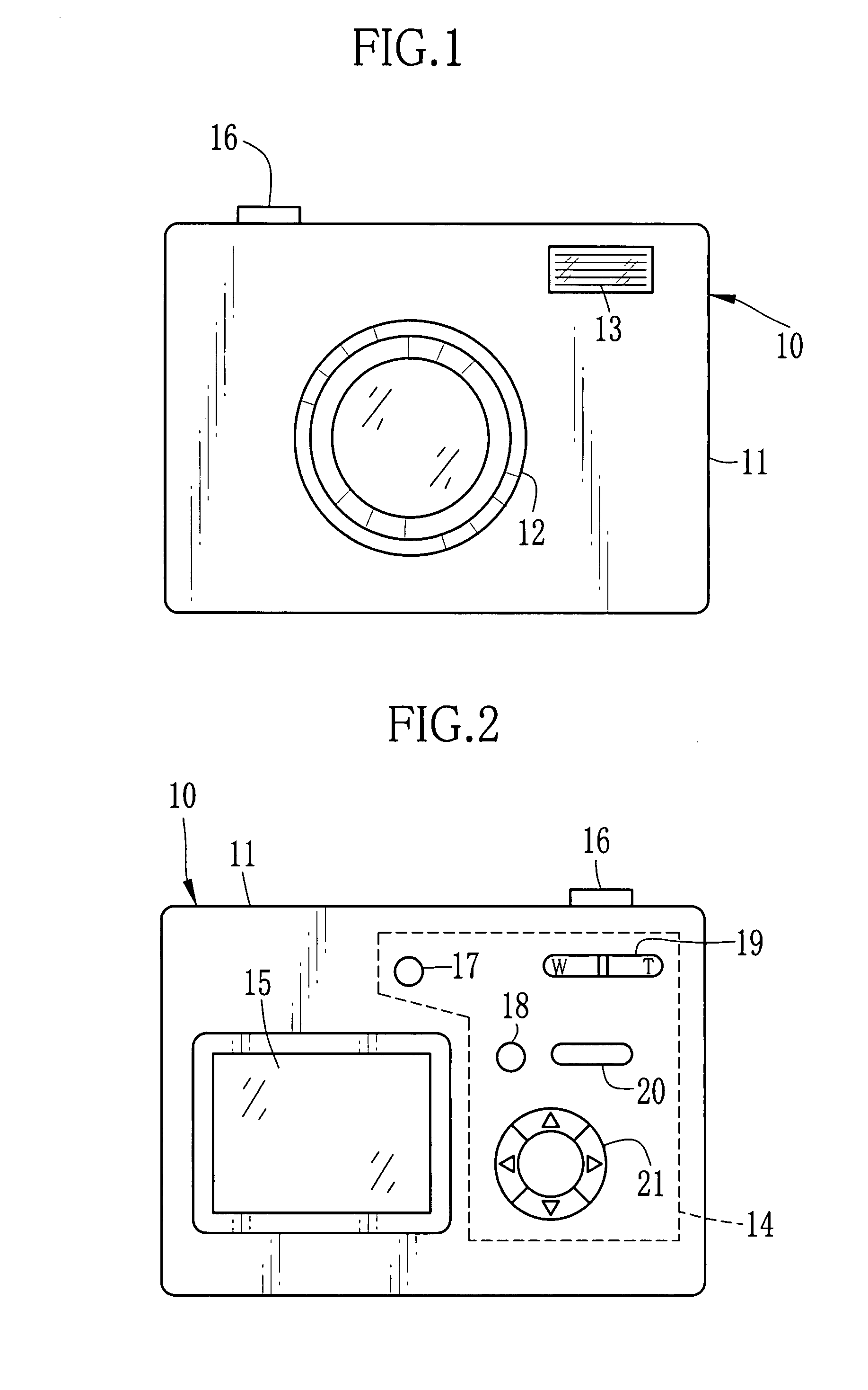
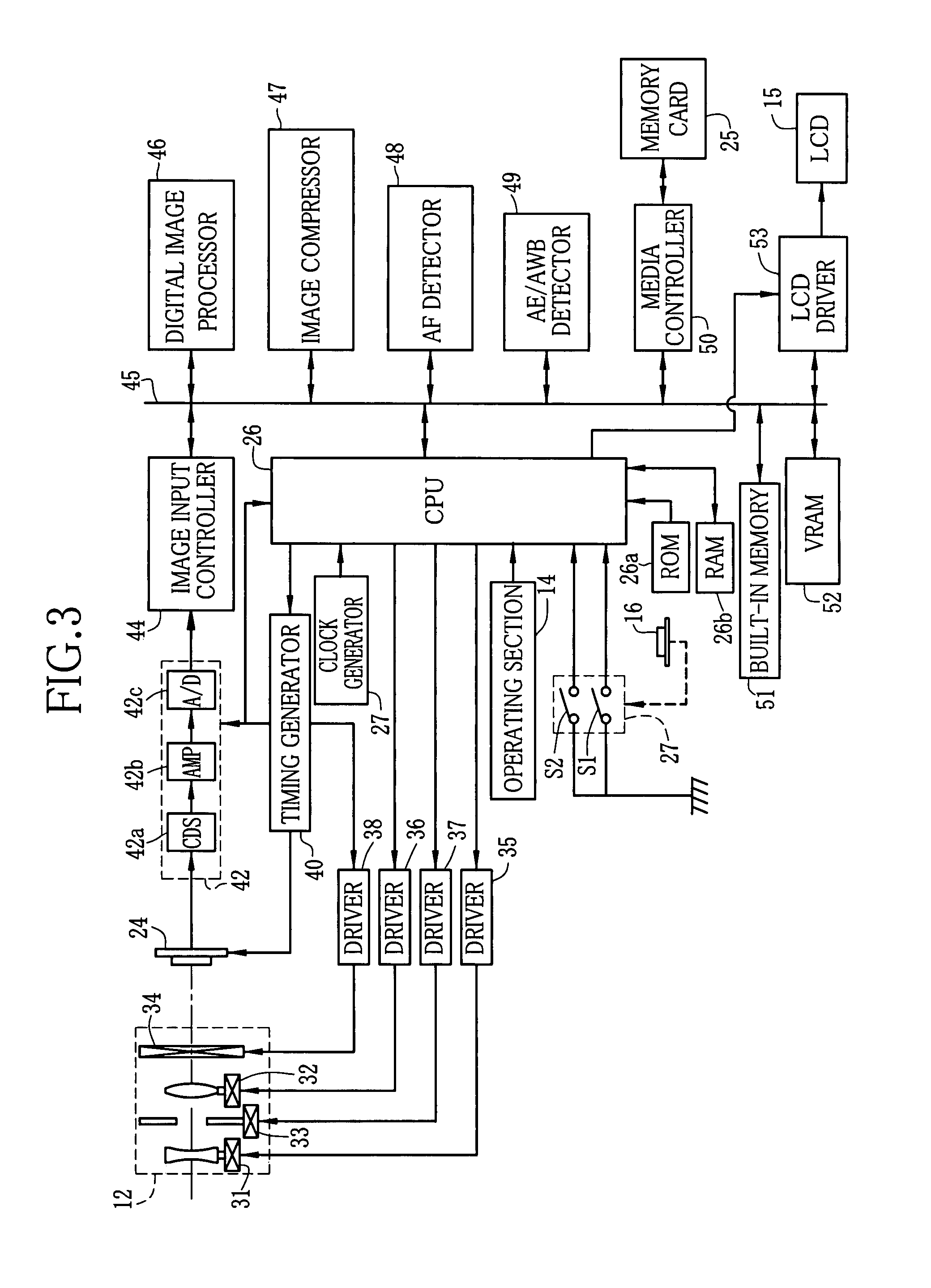
[0025]FIGS. 1 and 2 show front and back side views of a digital camera 10 embodying an imaging apparatus of the present invention, respectively. The digital camera 10 is provided with a taking lens 12 and a flash projector 13 on the front of a camera body 11, and with an operating section 14 consisting of various operating members and a LCD 15 as a display apparatus on the back. A release button 16 is provided on a top side of the camera body 11.

[0026]The operating section 14 consists of a power button 17, a mode button 18, a zoom button 19, a menu button 20 and a cross key 21. The power button 17 is to power on or off the digital camera 10 by a press operation. Upon each pressing operation, the mode button 18 switches over between a shooting mode for shooting and recording still images according to the press operation of the release button 16, and a reproducing mode for reproducing and displaying captured images on the LCD 15.

[0027]Operating the zoom button 19 in the shooting mode ...


PUM


Abstract

An LCD driver starts reading a digital image signal of one frame from a VRAM in response to a reproduction timing signal. A driving timing signal generator generates a driving timing signal in response to a synchronizing signal, whose phase is shifted by a delay time from the reproduction timing signal. So a phase difference corresponding to the delay time is provided between the driving timing signal and the reproduction timing signal. Synchronously with the driving timing signal, an image sensor is driven to shoot a subject and output an analog image signal of one frame. After being converted into a digital form, the image signal is written in the VRAM sequentially from the first line of one frame. The phase difference is determined so that the LCD driver starts reading the image signal sequentially from the first line, immediately after the first line is written in the VRAM.

Description

FIELD OF THE INVENTION[0001]The present invention relates to an imaging apparatus that displays a moving image of a subject that an image sensor is presently imaging, the image being called a camera-through image or live image.BACKGROUND OF THE INVENTION[0002]As a kind of imaging apparatus, digital cameras have been widely used. The digital camera images a subject through an image sensor such as a CCD image sensor. Many of the digital cameras are provided with a display device such as a LCD panel. The display device is not only used for displaying images reproduced based on captured image data, but also used as an electronic viewfinder for displaying the camera-through image. To display the camera-through image, the image sensor periodically outputs image signals at a predetermined frame rate, and the image frames obtained through the image sensor are sequentially displayed on the display device. Thus, the display device displays a moving image of a subject that exists in a shooting...

Claims


Application Information

Patent Timeline
Patent Type & Authority Patents(United States)
IPC IPC(8): H04N5/76
CPCH04N5/23293H04N7/0105H04N5/772H04N5/907H04N23/63
Inventor UCHIDA, AKIHIROTAKAHASHI, KEIICHIRO
Owner FUJIFILM CORP
Learn More