Systems and methods for determining level and/or type of a fluid

a technology of fluid level and type, applied in the direction of liquid/fluent solid measurement, instruments, machines/engines, etc., can solve the problems of electrical fluid level sensor electrical current associated with electrical fluid level sensor potential to introduce spark, safety-related issues, explosion hazards,

Inactive Publication Date: 2010-05-04
STRUBE
View PDF19 Cites 83 Cited by
  • Summary
  • Abstract
  • Description
  • Claims
  • Application Information

AI Technical Summary

Benefits of technology

[0015]Other methods comprise illuminating end faces of optical waveguides immersed in one or more types of fluids with optical energy, and measuring the optical energy that is transmitted through or reflected from interfaces of the one or more optical waveguides and the one or more types of fluids. The methods also comprise determining a level or levels of the one or more fluids based on (i) the optical energy that passes through or is reflected from the interfaces of the one or more optical waveguides and the one or more fluids, and (ii) relative locations of the end faces.
[0016]Other embodiments of systems comprise a plurality of optical waveguides each having an

Problems solved by technology

Electrical fluid-level sensors present safety-related issues in many applications.
For example, electrical fluid-level sensors have the potential to generate sparks, and thus present an explosion hazard when used in the presence of flammable fluids.
In particular, the electrical current associated with an electrical fluid-level sensor has the potential to introduce a spark due to, for example, chaffed insulation on the wiring that carries electrical current to or from the sensor.
Moreover, electrical sensors are susceptible to signal degradation in the presence of electromagnetic int

Method used


Image

  • Systems and methods for determining level and/or type of a fluid
  • Systems and methods for determining level and/or type of a fluid
  • Systems and methods for determining level and/or type of a fluid

Examples


Embodiment Construction

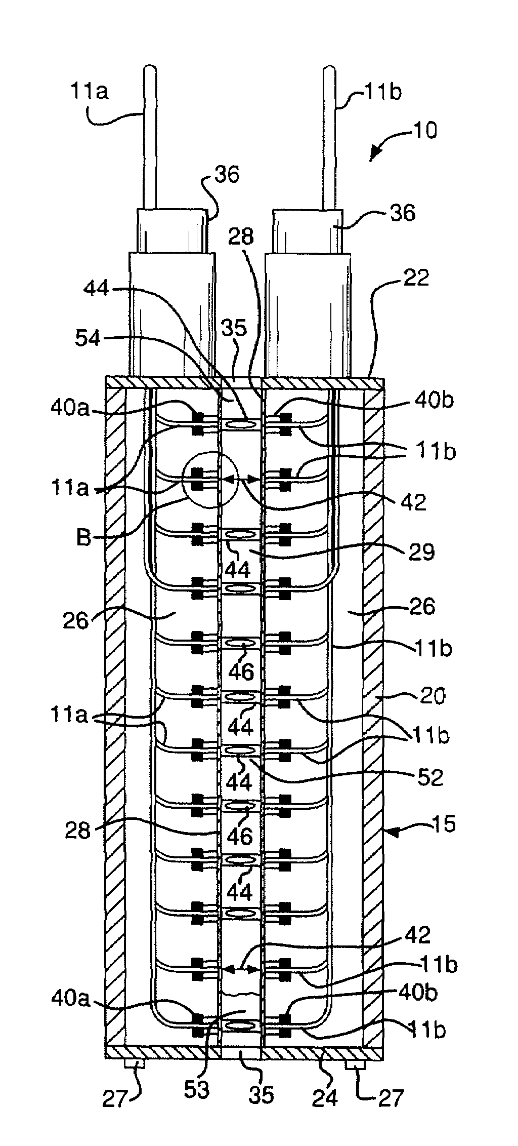
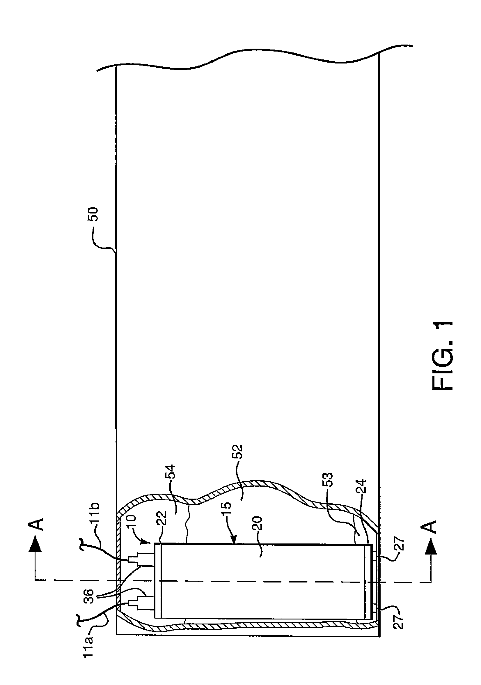
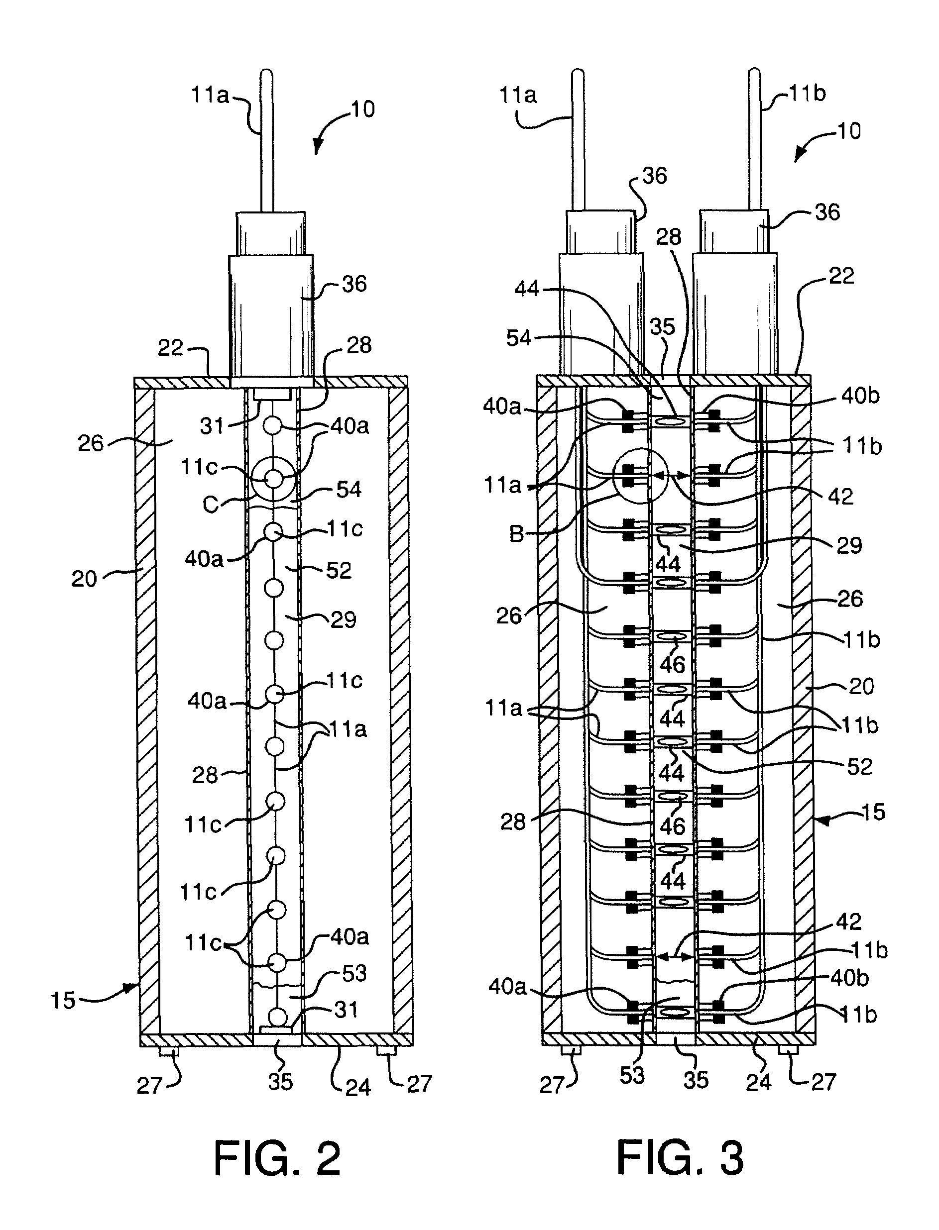
[0028]FIGS. 1-8 depict an embodiment of a system 10 for measuring the level of a fluid in a container such as a tank 50. The system 10 comprises a housing 15. The housing 15 is positioned within the tank 50 as depicted in FIG. 1, so that the fluid fully or partially immerses the housing 15.

[0029]The housing 15 includes a cylindrical body 20, a top portion 22, and a bottom portion 24. The body 20 can have other shapes in alternative embodiments. The top and bottom portions 22, 24 can be secured to the body 20 by a suitable means such as fasteners. The body 20, top portion 22, and bottom portion 24 define a volume 26 within the housing 15, as shown in FIGS. 2 and 3. The housing 15 can also include gaskets (not shown) positioned between the body 20 and each of the top and bottom portions 22, 24, to help seal the volume 26. Legs 27 can be attached to the bottom portion 24 to space the bottom portion 24 from the bottom surface of the tank 50, as shown in FIG. 1.

[0030]The housing 15 also ...


PUM


Abstract

Methods and systems are provided for determining the density and/or temperature of a fluid based on the manner in which optical energy is affected as the optical energy propagates across a gap between opposing end faces of optical waveguides, or the manner in which the optical energy is reflected from interfaces of optical waveguides and the fluid.

Description

[0001]This application claims priority under 35 U.S.C. §119(e) to U.S. provisional application No. 60 / 830,903, filed Jul. 14, 2006; and U.S. provisional application No. 60 / 782,583, filed Mar. 14, 2006. The contents of each of these applications is incorporated by reference herein in its entirety.TECHNICAL FIELD[0002]The present application relates to systems and methods for measuring the level of a fluid in a container, and / or identifying the type of fluid or fluids in the container.BACKGROUND[0003]A need to continuously measure the level of a fluid exists in many commercial and military applications. For example, fluid-level sensors are commonly used in the fuel tanks of aircraft, automobiles, and trucks. Fluid-level sensors are also used to monitor fluid levels within tanks utilized for fuel dispensing, wastewater treatment, chemical storage, food processing, etc.[0004]Electrical fluid-level sensors present safety-related issues in many applications. For example, electrical fluid-...

Claims


Application Information

Patent Timeline
IPC IPC(8): G01N21/00G01N21/59
CPCG01F23/2924G01F23/2927G01N21/8507G01N21/59G01N2021/8528
Inventor MENTZER, MARK A.PETRILLO, NICHOLAS P.WEBB, WAYNE A.TROSTLE, BRIAN S.
Owner STRUBE
Why Eureka
Try Eureka