Wellbores utilizing fiber optic-based sensors and operating devices

a fiber optic sensor and operating device technology, applied in the field of oilfield operations, can solve the problems of high cost, inability to provide continuous information about the condition of inability to provide continuous information about the wellbore or the surrounding formation, etc., and achieve the effect of high temperatur

Inactive Publication Date: 2006-05-09
BAKER HUGHES INC
View PDF58 Cites 120 Cited by
  • Summary
  • Abstract
  • Description
  • Claims
  • Application Information

AI Technical Summary

Benefits of technology

[0019]The distributed sensors of this invention find particular utility in the monitoring and control of various chemicals which are injected into the well. Such chemicals are needed downhole to address a large number of known problems such as for scale inhibition and various pretreatments of the fluid being produced. In accordance with the present invention, a chemical injection monitoring and control system includes the placement of one or more sensors downhole in the producing zone for measuring the chemical properties of the produced fluid as well as for measuring

Problems solved by technology

The above described methods are very expensive.
The wireline methods are utilized at relatively large time intervals, thereby not providing continuous information about the wellbore condition or that of the surrounding formations.
To obtain such measurements from the entire useful segments of each wellbore, which may have multi-lateral wellbores, requires using a large number of sensors, which requires a large amount of power, data acquisition equipment and relatively large space in the wellbore: this may be impractical or prohibitively expensive.
Because of the harsh operating conditions downhole, electrical cables are subject to degradation.
In addition, due to long electrical path lengths for downhole devices, cable resistance becomes significant unless large cables are used.
This is difficult to do within the limited space available in production strings.
In additio

Method used


Image

  • Wellbores utilizing fiber optic-based sensors and operating devices
  • Wellbores utilizing fiber optic-based sensors and operating devices
  • Wellbores utilizing fiber optic-based sensors and operating devices

Examples


Embodiment Construction

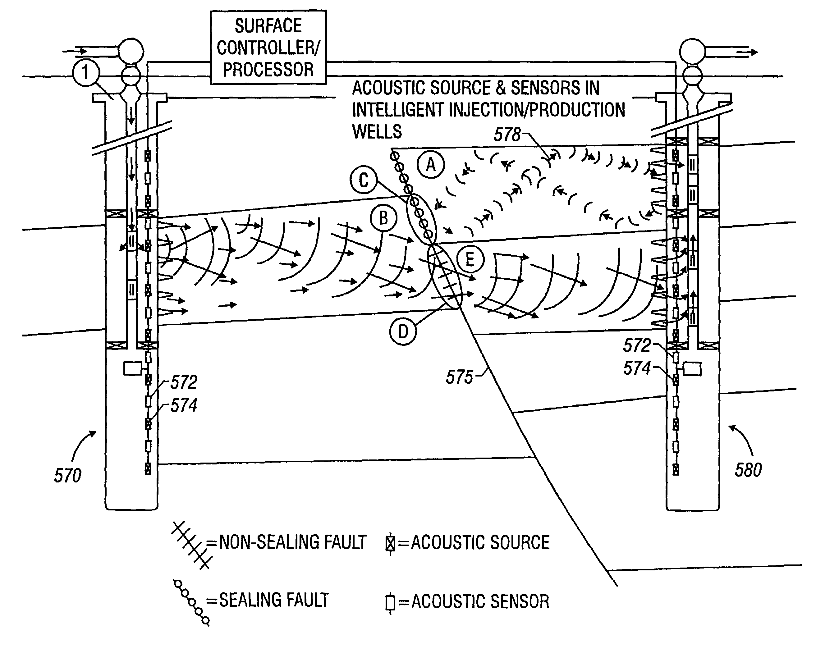
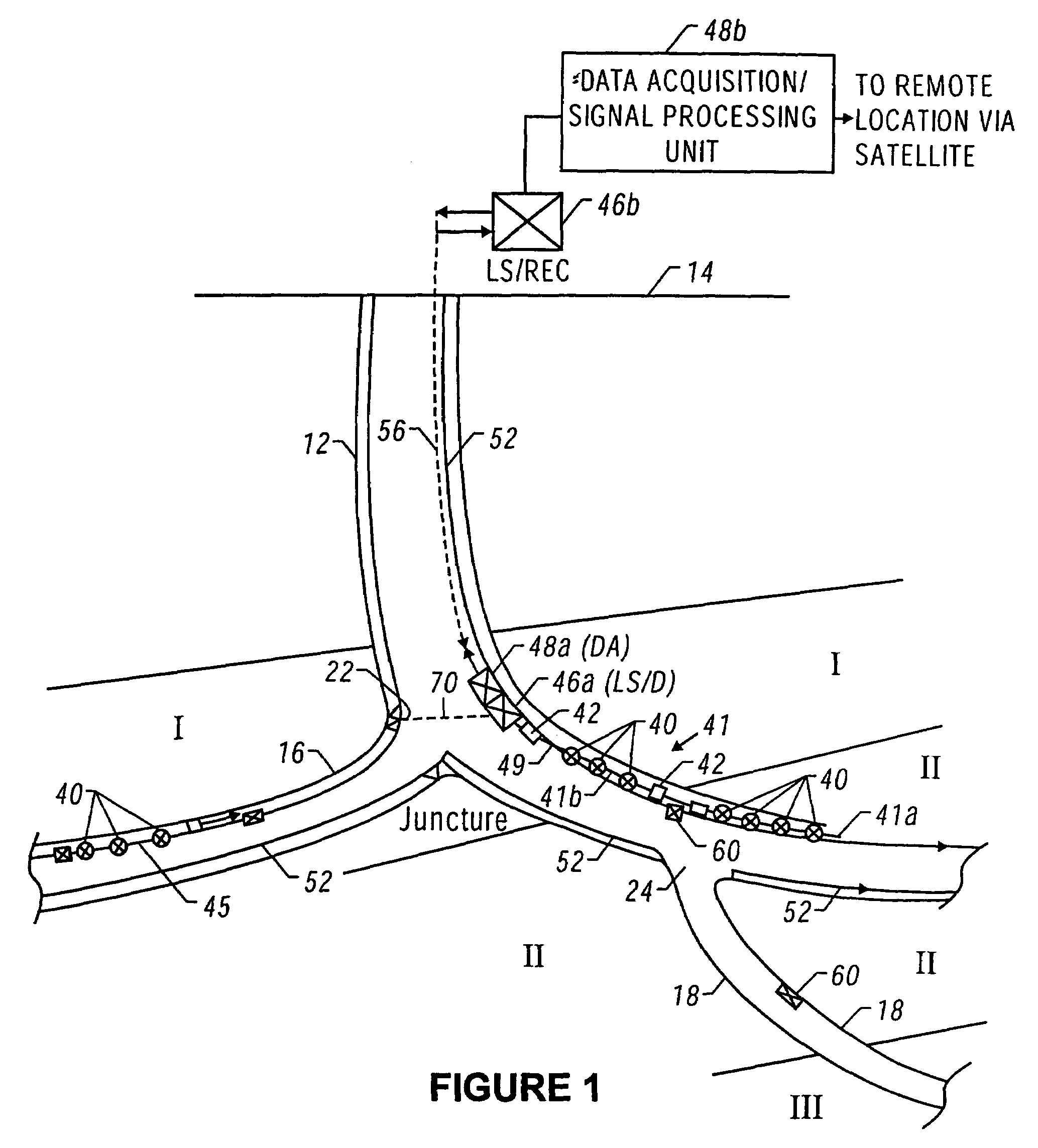
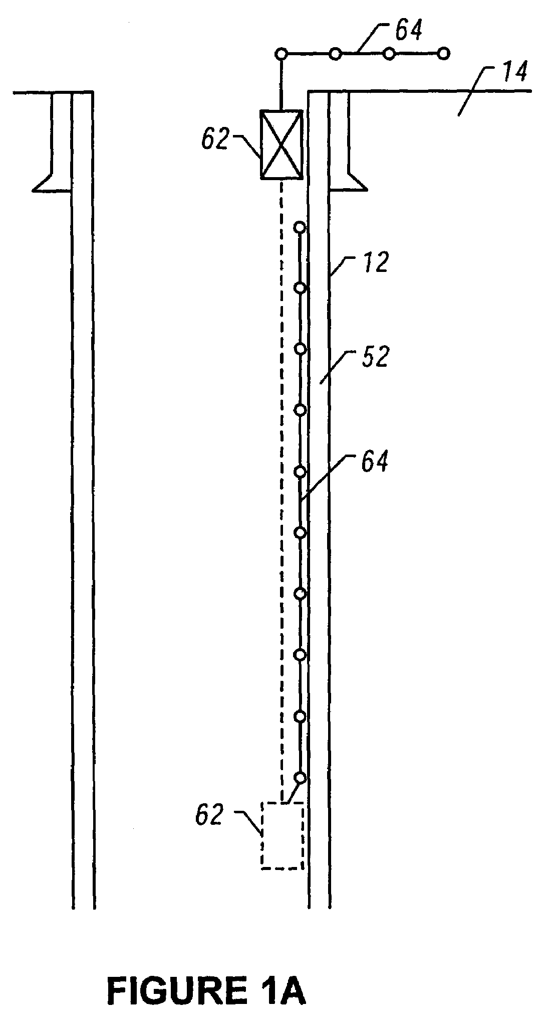
[0042]The various concepts of the present invention will be described in reference to FIGS. 1–17, which show a schematic illustrations of wellbores utilizing fiber optic-based sensors and operating devices.

[0043]FIG. 1 shows an exemplary main or primary wellbore 12 formed from the earth surface 14 and lateral wellbores 16 and 18 formed from the main wellbore 18. For the purpose of explanation, and not as any limitation, the main wellbore 18 is partially formed in a producing formation or pay zone I and partially in a non-producing formation or dry formation II. The lateral wellbore 16 extends from the main wellbore at a juncture 22 into the producing formation I, while the lateral wellbore 16 extends from the main wellbore 12 at juncture 24 into a second producing formation III. For the purposes of this illustration only, the wellbores herein are shown as being drilled on land; however, this invention is equally applicable to offshore wellbores. It should be noted that all wellbore ...


PUM


Abstract

This invention provides a method for controlling production operations using fiber optic devices. An optical fiber carrying fiber-optic sensors is deployed downhole to provide information about downhole conditions. Parameters related to the chemicals being used for surface treatments are measured in real time and on-line, and these measured parameters are used to control the dosage of chemicals into the surface treatment system. The information is also used to control downhole devices that may be a packer, choke, sliding sleeve, perforating device, flow control valve, completion device, an anchor or any other device. Provision is also made for control of secondary recovery operations online using the downhole sensors to monitor the reservoir conditions. The present invention also provides a method of generating motive power in a wellbore utilizing optical energy. This can be done directly or indirectly, e.g., by first producing electrical energy that is then converted to another form of energy.

Description

CROSS REFERENCE TO RELATED APPLICATIONS[0001]This application is a Divisional of U.S. patent application Ser. No. 10 / 121,375 now U.S. Pat. No. 6,787,758 filed on Apr. 12, 2002 which is a divisional of Ser. No. 09 / 778,696 filed on Feb. 6, 2001 (now U.S. Pat. No. 6,531,694) which is a divisional of U.S. patent application Ser. No. 09 / 071,764 filed on May 1, 1998 (the “Parent Application”), now U.S. Pat. No. 6,281,489. The parent application claimed priority from Provisional U.S. patent applications Ser. Nos. 60 / 045,354 filed on May 2, 1997; 60 / 048,989 filed on Jun. 9, 1997; 60 / 052,042 filed on Jul. 9, 1997; 60 / 062,953 filed on Oct. 10, 1997; 60 / 073425 filed on Feb. 2, 1998; and 60 / 079,446 filed on Mar. 26, 1998. Reference is also made to a United States patent application entitled “Monitoring of Downhole Parameters and Tools Utilizing Fiber Optics” filed on the same date as the present application under 09 / 071,764, the contents of which are incorporated here by reference.BACKGROUND OF...

Claims


Application Information

Patent Timeline
IPC IPC(8): E21B23/08E21B23/03E21B33/127E21B37/06E21B41/00E21B41/02E21B43/12E21B43/16E21B43/25E21B43/26E21B47/00E21B47/01E21B47/06E21B47/10E21B47/12E21B49/00E21B49/08G01D5/26G01N21/31G01V1/40G01V1/42G01V1/46G01V1/52G01V7/08G01V7/16G01V8/02G01V11/00
CPCE21B23/03G01V11/002E21B37/06E21B41/0035E21B41/02E21B43/12E21B43/122E21B43/123E21B43/16E21B43/25E21B43/26E21B47/00E21B47/011E21B47/06E21B47/065E21B47/10E21B47/101E21B47/1015E21B47/102E21B47/123E21B49/00E21B49/006E21B49/08G01D5/268G01N21/31G01V1/226E21B33/1275G01V1/52E21B47/107E21B47/017E21B47/07E21B47/11E21B47/135E21B47/114
Inventor TUBEL, PAULO S.JOHNSON, MICHAEL H.HARRELL, JOHN W.LEMBCKE, JEFFREY J.HICKEY, KURT A.
Owner BAKER HUGHES INC
Why Eureka
Try Eureka