

Ultrasonic atomizing nozzle and method
a technology of atomizing nozzle and ultrasonic nozzle, which is applied in the direction of spray nozzle, spray nozzle, spray nozzle, etc., can solve the problems of increasing the distance between the crest and trough of the capillary wave, and causing cavitation. to achieve the effect of promoting ultrasonic-frequency mechanical motion
- Summary
- Abstract
- Description
- Claims
- Application Information
AI Technical Summary
Benefits of technology
Problems solved by technology
Method used
Image

Examples
first embodiment
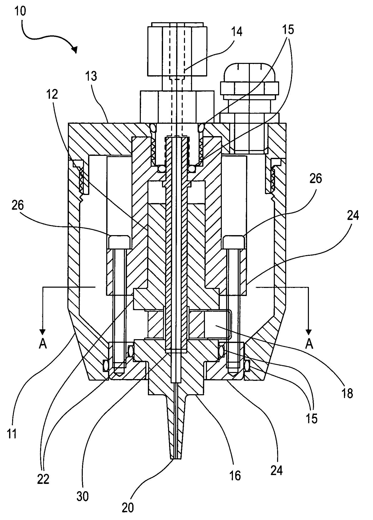
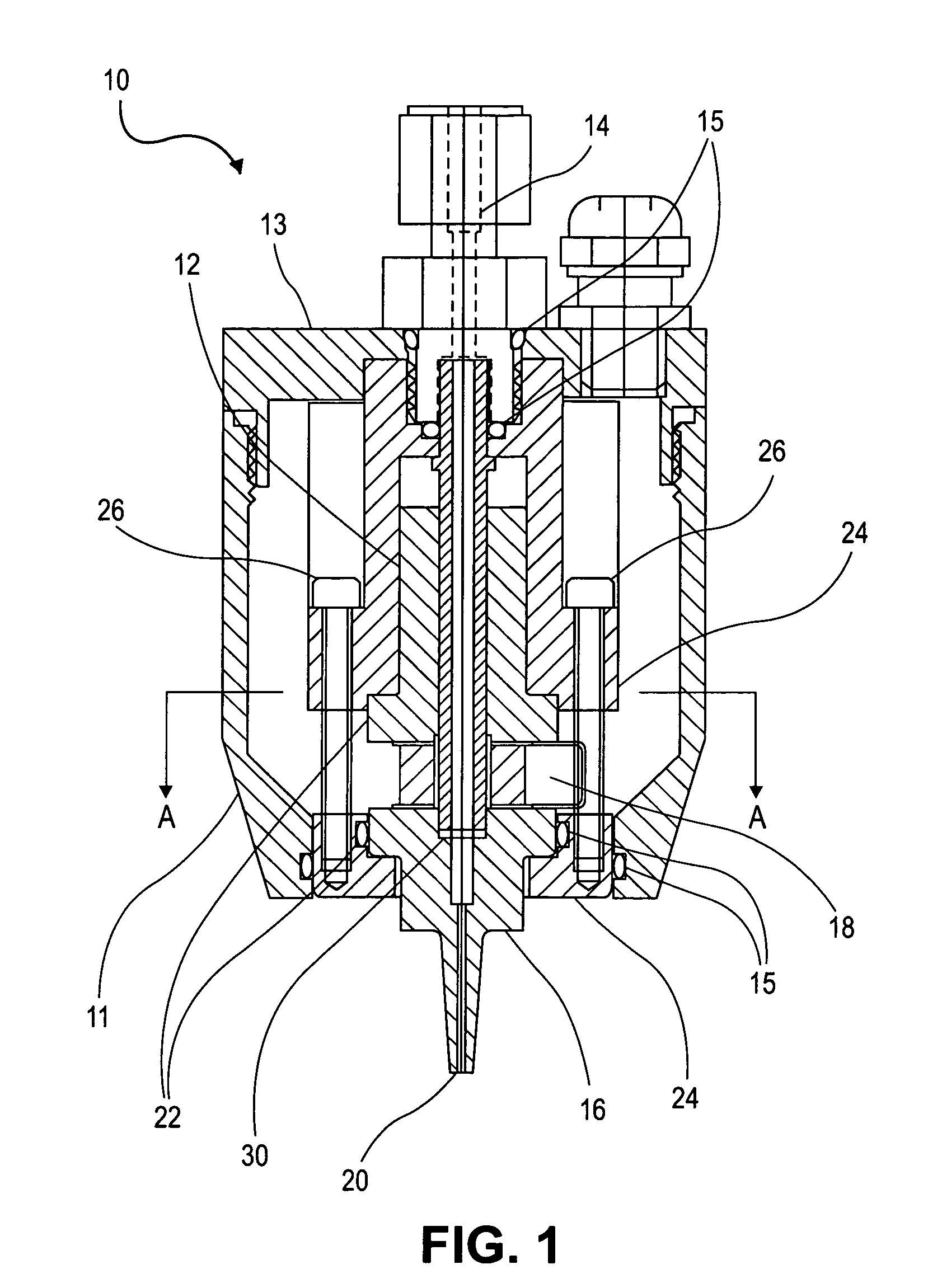
[0021]The invention will now be described with reference to the drawing figures, in which like reference numerals refer to like parts throughout. FIG. 1 is a longitudinal cross-sectional view of a ceramic-containing ultrasonic atomizing nozzle arrangement 10 according to the present invention. However, before further discussing the drawing figures any further, a few scientific principles related to ultrasonic atomization are briefly reviewed below.
[0022]Ceramic materials (e.g., SiC and Al2O3) differ from metals (e.g., titanium and titanium alloys) in a number of ways. For example, in some ceramic materials, such as silicon carbide (SiC) and aluminum oxide (Al2O3), the characteristic velocity at which sound waves propagate through these materials is considerably greater than the characteristic velocity at which sound waves propagate through any metallic material that is practical for use in constructing an ultrasonic atomizing nozzle. For example, SiC can be manufactured such that th...
second embodiment
[0041]FIG. 3 is a longitudinal cross-sectional view of an ultrasonic atomizing nozzle arrangement 32 according to the present invention. Like the nozzle 10 illustrated in FIG. 1, the nozzle 32 illustrated in FIG. 3 includes a liquid inlet 34, a rear horn 36 and a front horn 38, each having a flange 40. The front horn 38 also includes an atomizing surface 42 that is positioned at one end of a liquid conduit 44. In addition, the nozzle 32 illustrated in FIG. 3 includes a clamp arrangement that includes a plurality of rings 46 and bolts 48. Further, the nozzle 32 also includes a transducer portion 49 that includes a pair of transducers that are positioned in an intermediate section of the nozzle 32 that is located between the rear horn 36 and the front horn 38. Also illustrated in FIG. 3 are a front shroud 33 and a rear shroud 35 that, together, provide a housing for the nozzle 32 and a plurality of O-rings 37 that provide a plurality of seals within this housing.
[0042]One way in which...
third embodiment
[0043]FIG. 4 is a side view of a ceramic-containing ultrasonic atomizing nozzle 50 arrangement according to the present invention. Although only a front horn 52 and an atomizing surface 54 are illustrated in FIG. 4, the nozzle 50 illustrated in FIG. 4 also includes a rear horn, flanges, transducers and other components analogous to the components included in the nozzles 10, 32 illustrated in FIGS. 1-3. However, the nozzle 50 illustrated in FIG. 4 sits in a nozzle holder 56 that is positioned adjacent to a probe adjuster and holder 58. In turn, the probe adjuster and holder 58 is connected to a liquid delivery probe 60 that delivers liquid from a liquid input 62 to the atomizing surface 54. In other words, whereas liquid in the nozzles 10, 32 illustrated in FIGS. 1-3 traveled through the centers thereof before reaching the atomizing surfaces 20, 42, the nozzle 50 illustrated in FIG. 4 has liquid delivered directly to the atomizing surface 54 from a source exterior to the nozzle 50 (i...
PUM
 Abstract
Description
Claims
Application Information