Tool for chip removing machining as well as a basic body therefore

a technology for cutting machining and tools, which is applied in the direction of shaping cutters, manufacturing tools, twist drills, etc., can solve the problems of unreliable solution, lack of accurate repeatability, and difficult to carry out the internal machining of cemented carbide with good precision, and achieve good results in respect of dimensional accuracy and surface smoothness. , the effect of easy machin

Inactive Publication Date: 2010-05-11
SANDVIK INTELLECTUAL PROPERTY AB
View PDF6 Cites 58 Cited by
  • Summary
  • Abstract
  • Description
  • Claims
  • Application Information

AI Technical Summary

Benefits of technology

[0011]The invention is based on the idea of composing the basic body of the tool of two part bodies, one of which is a comparatively long, for example, cemented carbide body, and the other a shorter, for example, steel body in the form of a sleeve, which in a preferred embodiment includes female threads into which male threads of the first part body, as well as of the loose top may be fastened. In such a way, the awkward, internal fine finishing of the female threads, e.g., by turning and / or grinding, can be carried out in steel, which is easy to machine. Simultaneously, the male threads in the hard-to-be-machined cemented carbide in the first part body and the loose top, respectively, can be formed exclusively by external machining, which can be carried out with good results in respect of dimensional accuracy and surface smoothness.

Problems solved by technology

However, if the male and female coupling between the basic body and the loose top require grinding or another precision machining, such as is the case with thread couplings, problems arise, because internal machining in cemented carbide is difficult, if not impossible, to carry out with good precision.
However, this solution has turned out to be unreliable because soldering is a manual operation, which lacks accurate repeatability.
In other words, the important coaxiality between the steel body and the cemented carbide body may be difficult to attain.
In addition, the soldered seam forms in practice a permanent joint, which entails that the basic body in its entirety has to be discarded also in such cases when only the front steel body is damaged, but not the rear cemented carbide body.
However, the shrink fit has the disadvantage that replacement of worn loose tops become highly intricate and time-consuming.
In addition, the coaxiality of the loose top and basic body may be impaired if the generation of heat in the tool becomes great.

Method used


Image

  • Tool for chip removing machining as well as a basic body therefore
  • Tool for chip removing machining as well as a basic body therefore
  • Tool for chip removing machining as well as a basic body therefore

Examples


Embodiment Construction

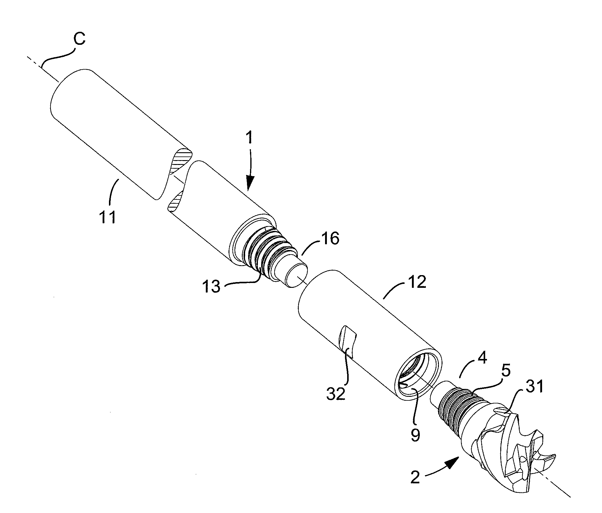
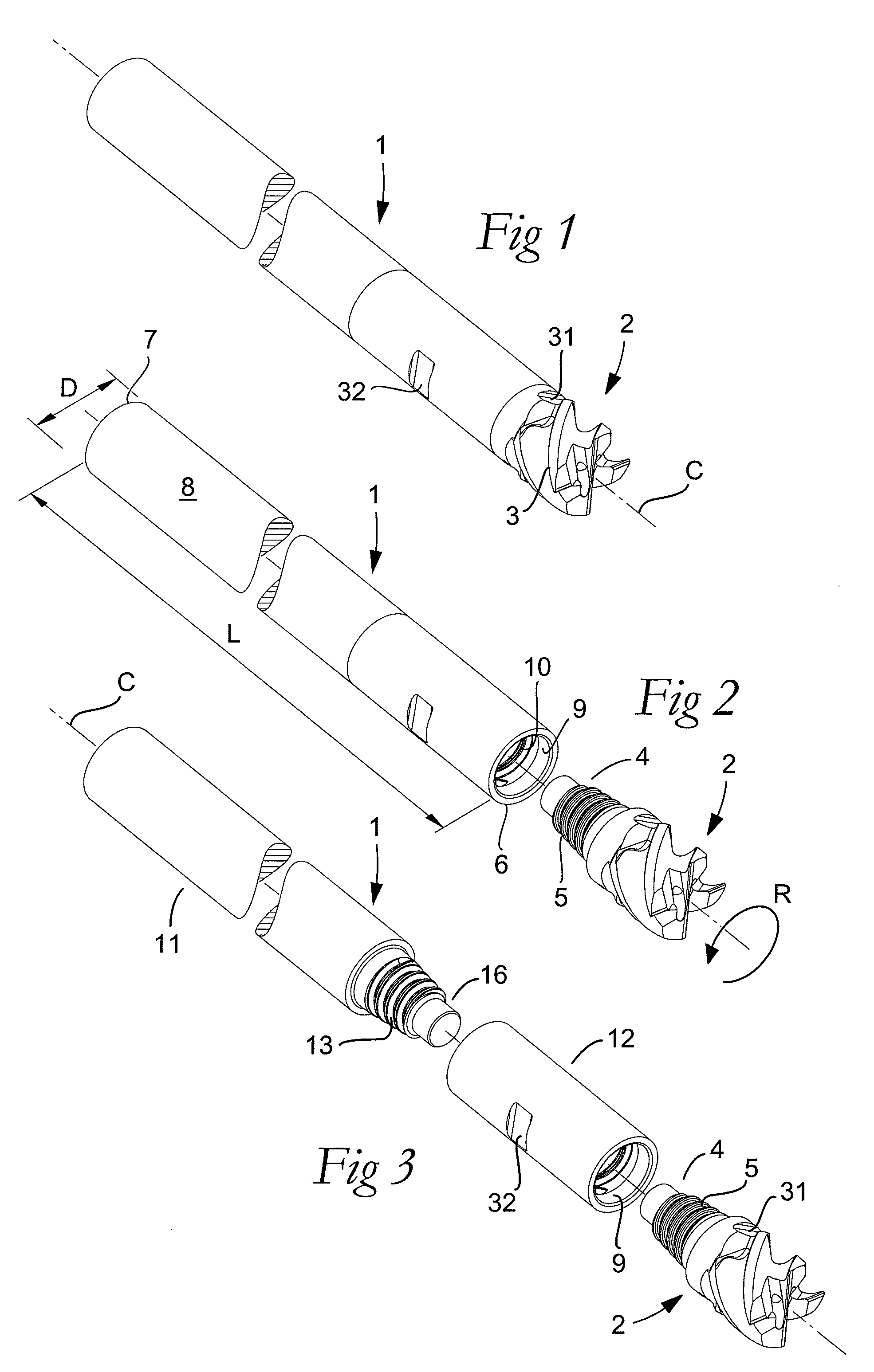
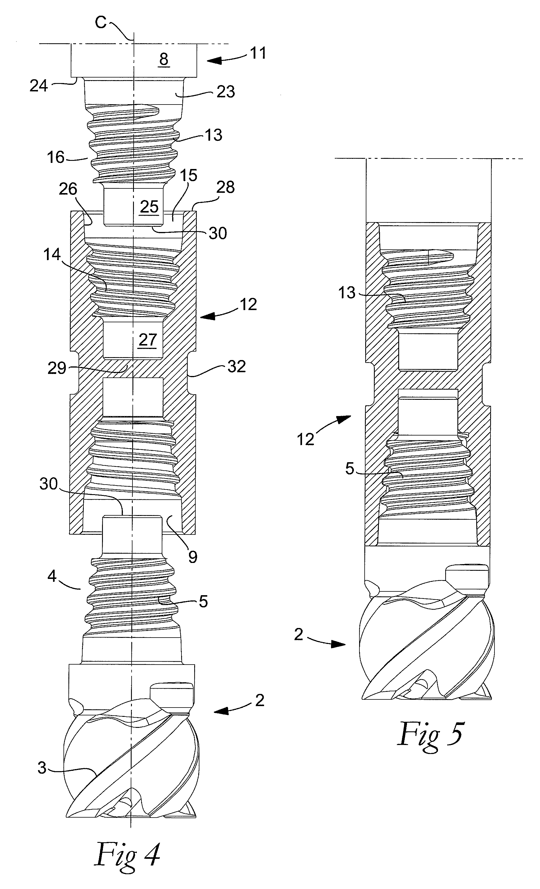
[0019]The exemplified tool shown in the drawings is in the form of a shank-end mill, which includes a basic body 1 and a replaceable wear body or loose top 2. In the last-mentioned one, a number of cutting edges 3 for the chip removing machining are included. In the rear end thereof, the loose top is formed with a male element 4 in which a male thread 5 is included for the connection of the loose top with the basic body. Advantageously, the loose top 2 is in its entirety manufactured from cemented carbide or another hard material, such as cermet, ceramics or the like. The tool is rotatable around a center axis C, more precisely, in the direction of rotation R.

[0020]The basic body 1 has a long narrow, rotationally symmetrical basic shape and extends between front and rear ends 6 and 7, respectively, the envelope surface 8 thereof being concentric with the center axis C. In the front end 6, a seating 9 mouths, in the interior of which a female thread 10 is formed for the co-operation ...


PUM

PropertyMeasurementUnit
diametersaaaaaaaaaa
modulus of elasticityaaaaaaaaaa
axial forcesaaaaaaaaaa

Abstract

A tool for chip removing machining, including a long narrow basic body having an envelope surface which is concentric with a center axis, and two opposite ends, and a replaceable loose top which is connected to the basic body via a first coupling that includes a first seating formed in one end of the basic body and a first male element formed in one end of the loose top. The basic body includes a primary part body made of a first material having a first modulus of elasticity, and a secondary part body which includes the first seating and is made of a second material having a second modulus of elasticity which is lower than the first modulus of elasticity. The two part bodies of the basic body are interconnected via a second coupling which includes a second seating in the secondary part body as well as a second male element that is formed on the primary part body and has one or more precision machined flank surfaces that are arranged to apply, together with one or more co-operating and precision machined flank surfaces of the second seating, joining axial forces to the part bodies by turning the part bodies in relation to each other.

Description

[0001]This application claims priority under 35 U.S.C. §119 to Swedish Patent Application No. 0701368-3, filed on Jun. 5, 2007, which is incorporated by reference herein in its entirety.FIELD OF THE INVENTION[0002]The present invention relates generally to a tool for chip removing or cutting machining of the type that includes, on one hand, a long narrow basic body having an envelope surface, which is concentric with a center axis, and two ends, and on the other hand a replaceable loose top, which is connected to the basic body via a coupling that includes a seating formed in one end of the basic body and a male element formed in one end of the loose top, the basic body being composed of a primary part body of cemented carbide or a similar material having a first, high modulus of elasticity, as well as a secondary part body, which includes the seating and is made of steel having a second modulus of elasticity which is considerably lower than the first one. The invention also relates...

Claims


Application Information

Patent Timeline
Patent Type & Authority Patents(United States)
IPC IPC(8): B23B51/02B23B51/06
CPCB23B31/005B23B31/1107B23B31/1115B23B51/00B23C5/10B23B2222/28B23B2222/84Y10T407/1906B23C2210/02B23C2210/03Y10T407/2268Y10T407/19B23B2251/02B23B27/16B23C5/22B23B51/0004B23B51/0003B23C2240/24
Inventor LEHTO, RALFORTLUND, MAGNUSKAKAI, ISAK
Owner SANDVIK INTELLECTUAL PROPERTY AB
Why Eureka
Try Eureka