Submersible pump apparatus and method for using same

a technology of pump apparatus and submerged pump, which is applied in the field of submersible pumps, can solve the problems of difficult installation, device easy to be easily turned over or flipped, and devices that cannot be easily cleaned, etc., and achieve the effects of positive buoyancy, negative buoyancy, and positive buoyancy

Active Publication Date: 2010-05-11
AQUA CONTROL
View PDF16 Cites 24 Cited by
  • Summary
  • Abstract
  • Description
  • Claims
  • Application Information

AI Technical Summary

Problems solved by technology

The problem with the above devices and, in particular, the devices that are along the bottom surface of the water is that: (1) the devices can be difficult to install in the correct position and orientation in a body of water; (2) the devices are susceptible to being easily turned over or flipped when being installed or while in operation; (3) the devices often cannot be easily accessed for cleaning once installed; (4) the devices are difficult to move or be reoriented; (5) the devices are difficult to remove from the body of water; and / or (6) if the silt depth is unknown, the devices do not disclose a means for preventing the device from sinking or being absorbed into the silt depth and being rendered useless.

Method used


Image

  • Submersible pump apparatus and method for using same
  • Submersible pump apparatus and method for using same
  • Submersible pump apparatus and method for using same

Examples


Embodiment Construction

will be better understood with reference to the following figures:

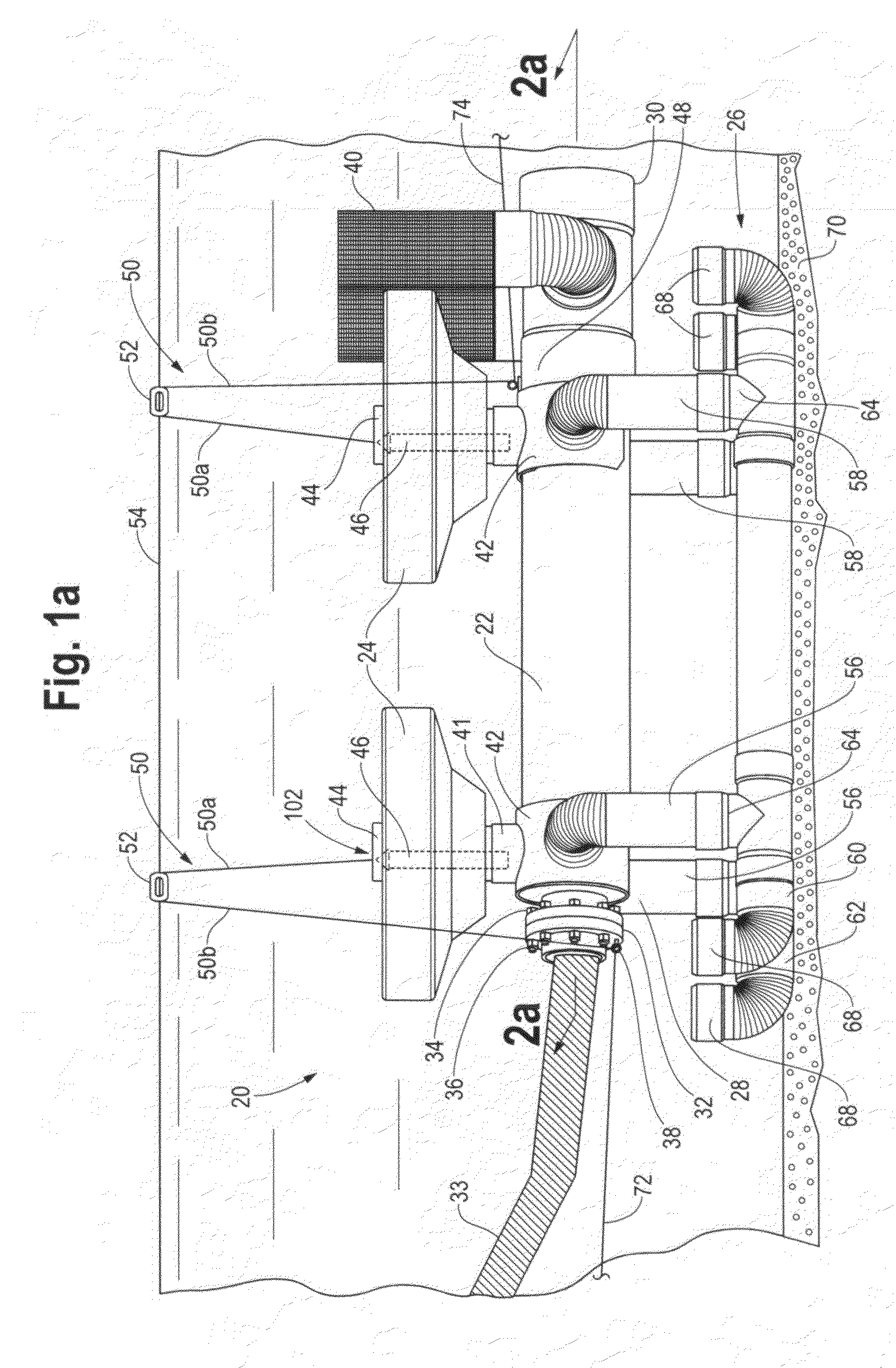
[0019]FIG. 1a is a side perspective view of Applicant's submersible pump apparatus.

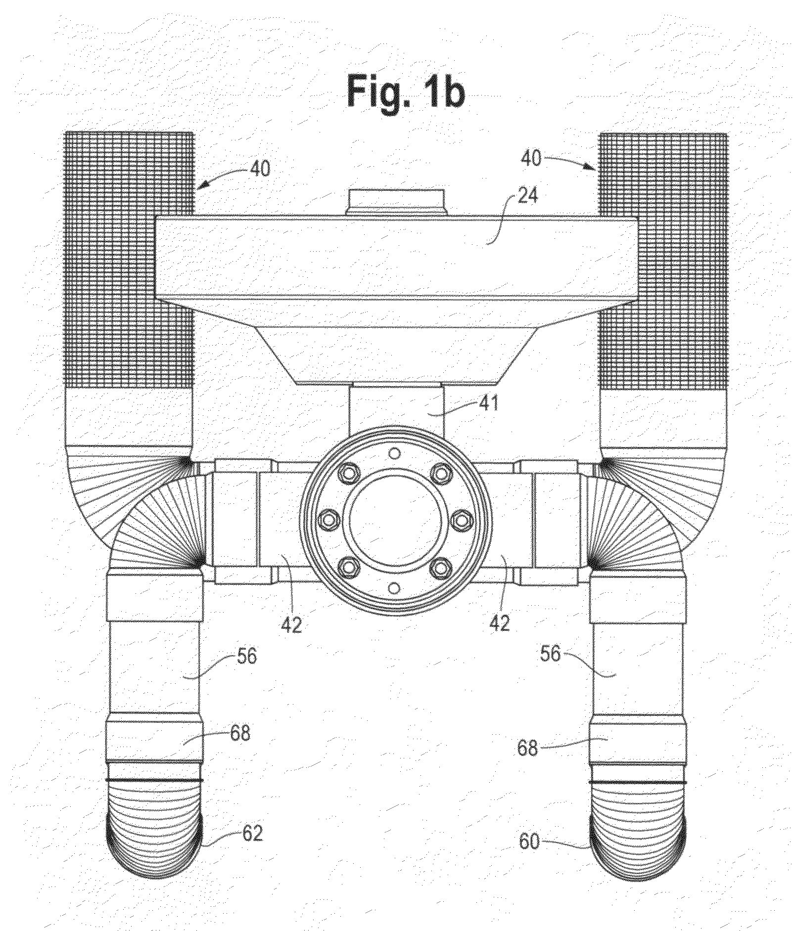
[0020]FIG. 1b is an end view of the submersible pump apparatus.

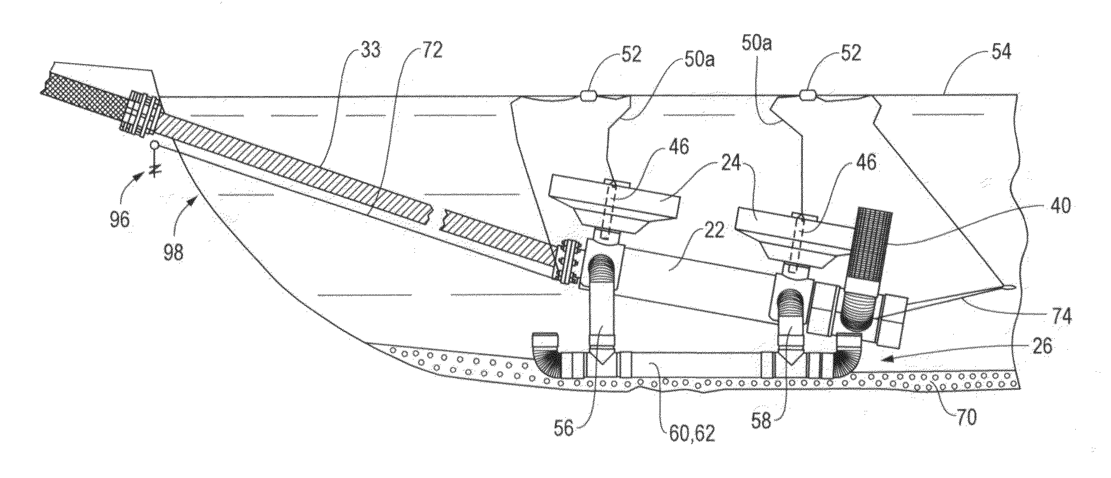
[0021]FIG. 2a is a cross sectional view, taken along line 2a-2a of FIG. 1a, illustrating, in particular, the pump assembly contained within the housing and the receiving channel contained within the floats.

[0022]FIG. 2b is a side perspective view, with portions removed, of the float and the receiving channel contained within the float.

[0023]FIG. 2c is a side perspective view of the weight that is received into the receiving channel of the floats.

[0024]FIG. 3 is a side perspective view of the submersible pump apparatus at it resides at the water surface level while in the process of being installed in a body of water.

[0025]FIG. 4 is a side perspective view of the submersible pump apparatus at it resides at the bottom of the body of water upon being installed.

[0026]FIG. 5a is ...


PUM


Abstract

A submersible pump apparatus comprising a housing containing all the components of the pump assembly for using the submersible pump apparatus in a body of water. A float or a plurality of floats are attached to the top side of the housing for providing a positive buoyancy to the submersible pump apparatus. The float is provided with a channel for slidably receiving a single weight or a plurality of weights. The weight is used to overcome the positive buoyancy of the float and achieve a negative buoyancy for submerging the submersible pump apparatus to the bottom of the body of water. A sled is attached to the bottom side of the housing and comprises the combination of both legs and feet for supporting the submersible pump apparatus at the bottom of a body of water. A finder float floating at the water surface level is attached using a rope to both the weight and the housing. By removing the weight or weights from the float, a positive buoyancy is restored to raise the submersible pump apparatus.

Description

I. FIELD OF THE INVENTION[0001]The present invention relates to submersible pumps and, more particularly, to a submersible pump apparatus that is uniquely designed to be installed, used, and retrieved from a body of water.II. DESCRIPTION OF THE PRIOR ART[0002]Submersible pumps such as circulation or aeration devices are commonly used for creating directional flow in a pond or lake to turn still, stagnant water into a stream environment. This helps, among other things, to add vital oxygen to the water and improve pond or lake aeration; reduce aquatic plant growth and inhibit mosquito reproduction; and protect permanent fixtures in the water such as docks, etc . . .[0003]Some examples of circulation or aeration devices are disclosed in the following identified patents, listed below by order of issuance.[0004]InventorIssuedTitle of PatentU.S. Pat. No.TormaschyAug. 27, 2002Water Circulation Apparatus and Method6,439,853WegnerJun. 05, 2001Waste Pond Liquid Circulation System6,241,221Havi...

Claims


Application Information

Patent Timeline
Patent Type & Authority Patents(United States)
IPC IPC(8): F04B53/00
CPCF04B19/04
Inventor DANE, WILLIS
Owner AQUA CONTROL
Why Eureka
Try Eureka