Video endoscope with a rotatable video camera

a video camera and endoscope technology, applied in the field of video endoscopes, can solve the problems of degrading focus, affecting the accuracy of endoscopes, so as to achieve high resolution, precise focusing distance, and good focus

Active Publication Date: 2010-05-11
OLYMPUS WINTER & IBE
View PDF12 Cites 107 Cited by
  • Summary
  • Abstract
  • Description
  • Claims
  • Application Information

AI Technical Summary

Benefits of technology

[0009]In the present invention, the distal swivel bearing is designed for axial bearing. In this manner, the video camera is always reliably at the precise focusing distance from the objective lens, whereas the proximal end of the rotational element is allowed to easily move axially on account of being bent or undergoing temperature changes. In this manner, good focus is assured under all possible conditions.
[0010]In further accordance with the present invention, the distal swivel bearing is a simple slide bearing. The required space, in particular in the radial direction, is small, and as a result a large-area and hence highly resolving video camera may be used even when the outside diameter of the video endoscope is small. By using a ceramic slide ring, the tube and the camera are electrically insulated, keeping the patient safe from electrical shock or exposure.
[0011]If the ceramic ring were to fit precisely into the external groove, jamming might occur, for instance, if the temperatures were to change. Accordingly, the present invention advantageously provides some play in both guide directions. A few hundredths of a mm are adequate for this purpose and do not significantly hamper optical alignment and focusing. This design offers the significant advantage that no stresses are exerted on the ceramic ring in the external groove and, accordingly, the ring swivels very freely. Therefore the video camera allows fine manual control and is free from jerky motion.
[0012]If the entire objective lens were fixed, every play of the video camera relative to the tube would interfere with the proper imaging on said camera. Accordingly, in the present invention a proximal portion of the objective lens is affixed to the camera to be swiveling jointly with it and, consequently, to be lined up entirely free of play relative to the camera. The two portions of the objective lens may be designed such that a substantially collimated beam, which is insensitive to radial and axial shifts, shall be set up between them. In this way the imaging quality is substantially increased regardless of deviations due to play and adjustments.

Problems solved by technology

This known design incurs the drawback that the axial bearing is situated at the proximal end of the swivel element.
If the endoscope is being bent and when there are temperature changes such as frequently occur when using video endoscopes (body temperature / room temperature), the distance between objective lens and video camera may change and degrade the focus, i.e., they may entail a blurred picture.

Method used


Image

  • Video endoscope with a rotatable video camera
  • Video endoscope with a rotatable video camera
  • Video endoscope with a rotatable video camera

Examples


Embodiment Construction

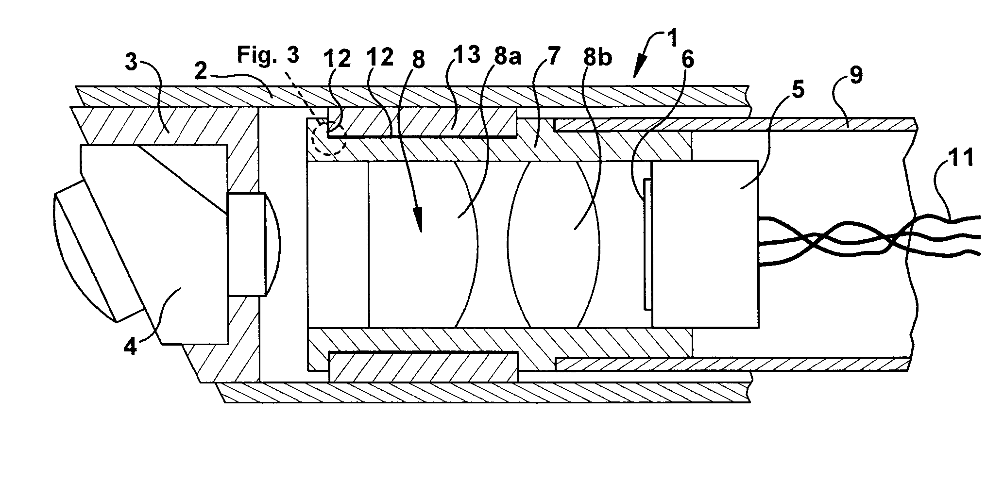
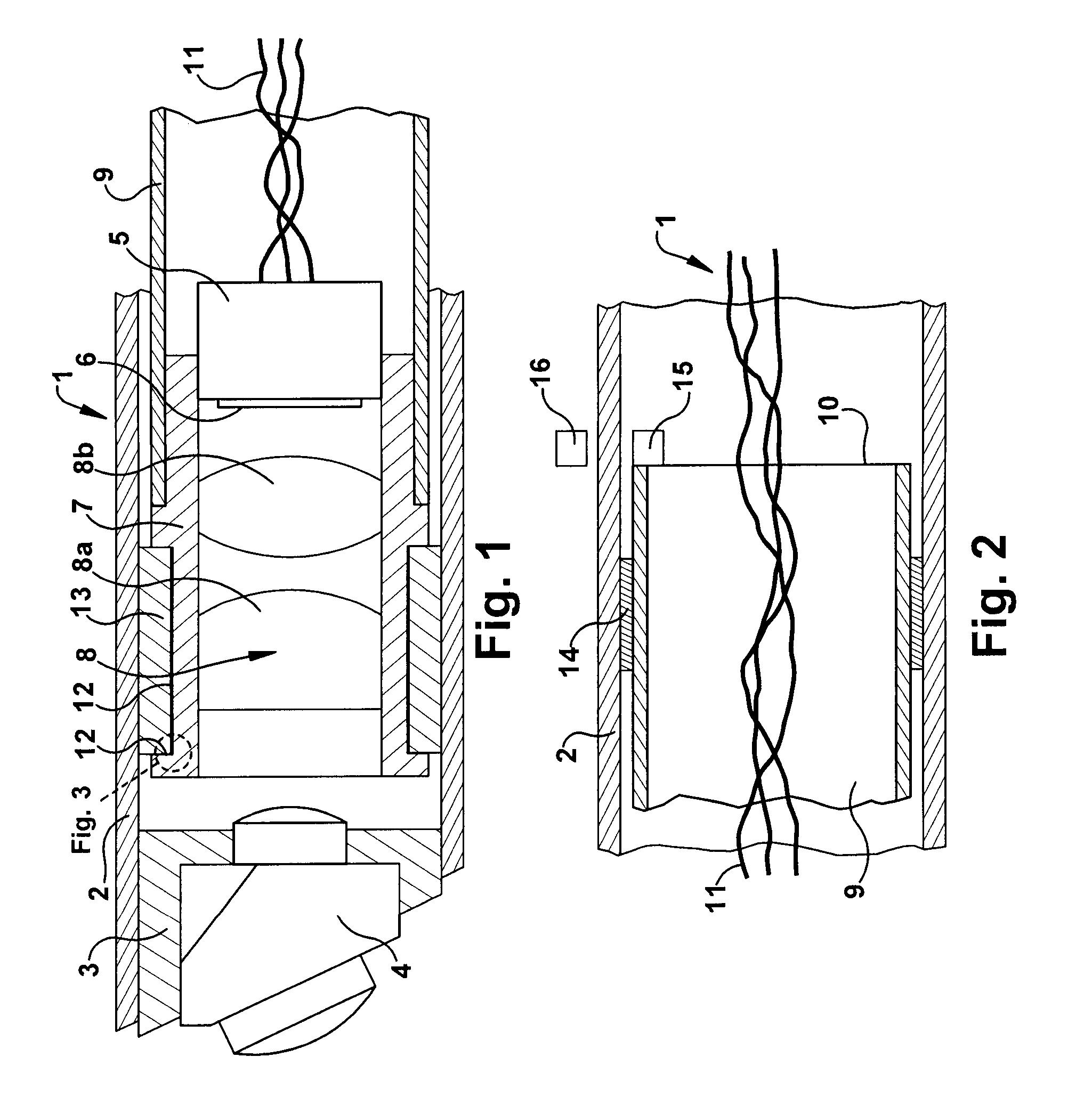
[0017]FIG. 1 shows the distal end zone of the significant portions of a video endoscope 1. An objective lens fixture 3 is affixed in a tube 2 at the far distal end and holds a distally fixed portion 4 of the objective lens. In the shown embodiment, the distal objective lens portion 4 consists of a prism and two lens elements. A video camera 5 with an imaging detector plate 6 is affixed in an annular camera case 7 which, moreover, contains two lens elements 8a and 8b that constitute a proximal portion 8 of the objective lens.

[0018]A rotating tube 9 constituting a rotating drive element is affixed to the camera case 7 and runs through the tube 2 as far as the proximal end zone (FIG. 2) where it terminates at 10. Hookup cables 11 of the video camera 5 run through the rotating tube 9.

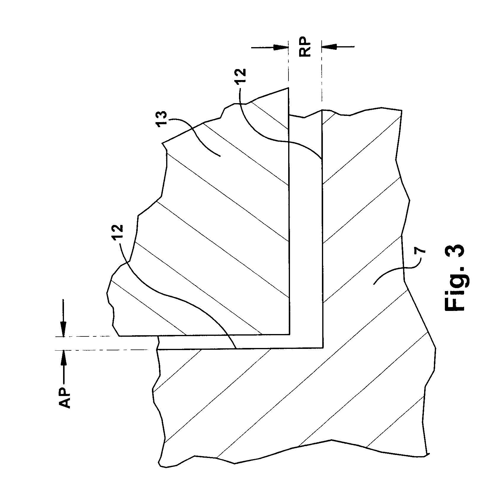
[0019]The camera case 7 is fitted with an external groove 12 by means of which it is guided in sliding manner in a ceramic ring 13 which, in turn, is affixed in the tube 2. The camera case 7 and, jointly wi...


PUM


Abstract

A video endoscope includes a tube fitted at its distal end with an affixed objective lens, a video camera mounted behind the objective lens in the tube, the camera together with an elongated rotation element constituting a swivel unit that is supported both at the distal and proximal end zones in each case by swivel bearing at the tube. The swivel element being rotationally adjustable relative the tube by a swivel drive system. The distal swivel bearing is axially and radially bearing and the proximal swivel bearing is only radially bearing.

Description

BACKGROUND OF THE INVENTION[0001]1. Field of the Invention[0002]The present invention generally relates to a video endoscope and, more particularly, toward an endoscope with a rotatable video camera.[0003]2. Description of Related Art[0004]When used in procedures in the human body, endoscopes frequently need to be rotated or swiveled so that an implement fitted into the endoscope may reach a particular place or, for instance, to be able to observe laterally when the objective lens is oblique. When the video camera however is irrotationally mounted in the video endoscope, the monitor picture shall rotate jointly with the video endoscope. This feature is highly taxing for the surgeon.[0005]Accordingly video endoscopes of this kind are fitted with a rotatable camera which can be rotated relative to the video endoscope rotation such that the monitor picture shall remain unaffected by camera rotation.[0006]The German patent document U 20,113,031 discloses a video endoscope wherein, on we...

Claims


Application Information

Patent Timeline
Patent Type & Authority Patents(United States)
IPC IPC(8): A61B1/04
CPCA61B1/00183G02B23/2423A61B1/053A61B1/05
Inventor HANKE, HARALD
Owner OLYMPUS WINTER & IBE
Why Eureka
Try Eureka