Wind energy harvesting system on a frozen surface

a technology of wind energy and harvesting system, which is applied in the direction of renewable energy generation, electric generator control, greenhouse gas reduction, etc., can solve the problems of increasing ocean water levels, reducing the efficiency of wind energy harvesting, and reducing the environmental impact of fossil fuels to meet current and emerging energy needs, so as to achieve efficient and cost-effective effects

Active Publication Date: 2010-05-11
RIC ENTERPRISES
View PDF32 Cites 13 Cited by
  • Summary
  • Abstract
  • Description
  • Claims
  • Application Information

AI Technical Summary

Benefits of technology

[0005]The present invention provides a renewable energy harvesting system for harvesting wind energy on a frozen surface, as in cold weather climate regions associated with higher latitudes and / or higher altitudes, also taking seasonality effects into consideration. The present invention is intended to provide devices, methods and systems for harvesting renewable energy which can be efficient and cost-effective for small-scale, medium-scale and large-scale applications, to provide real and substantial benefits to meet local energy needs while also more broadly serving humanity and our global environment.

Problems solved by technology

The continued use of fossil fuels to meet current and emerging energy needs also has very negative environmental consequences, including massive emissions of pollutants and exacerbation of global warming and climate change.
It would be highly beneficial to use wind energy to meet these energy needs with a renewable local source, since direct solar energy is not a viable alternative in high latitude winter seasons.
The use of efficient wind power in such climes will not only meet energy hunger in these locales, but do so without any greenhouse gas emissions and without any local thermal powerplants dumping heat and greenhouse gases into what may be amongst the most vulnerable locales for the adverse effects of global warming—with these locales being most susceptible to greenhouse gas and global warming induced ice and snow melting, and the consequent long term adverse effect of increasing ocean water levels on a global scale.

Method used


Image

  • Wind energy harvesting system on a frozen surface
  • Wind energy harvesting system on a frozen surface
  • Wind energy harvesting system on a frozen surface

Examples


Embodiment Construction

[0037]The invention can be better understood through a full consideration of the Figures illustrating preferred embodiments of the invention, along with the following detailed description with reference to these Figures.

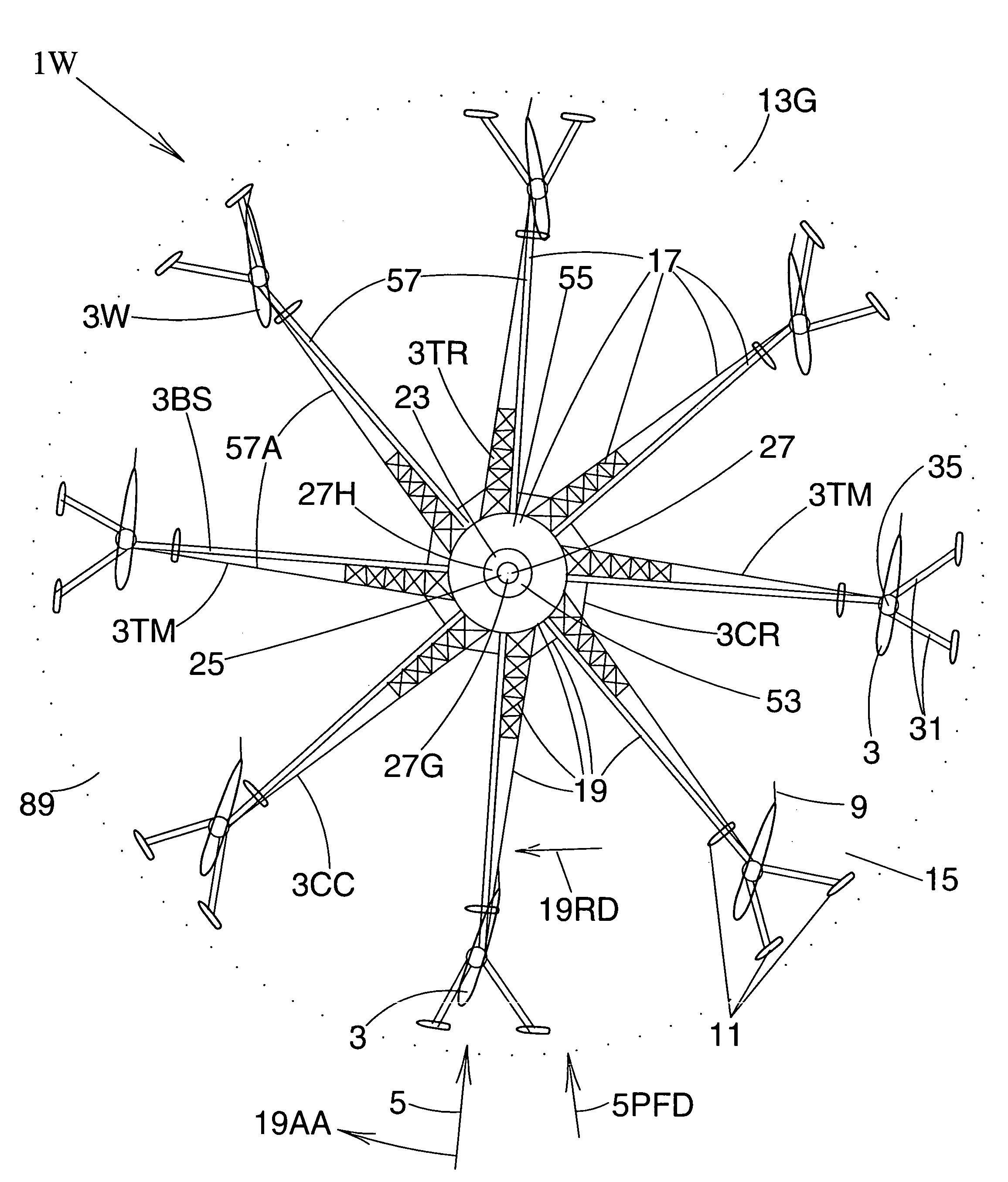
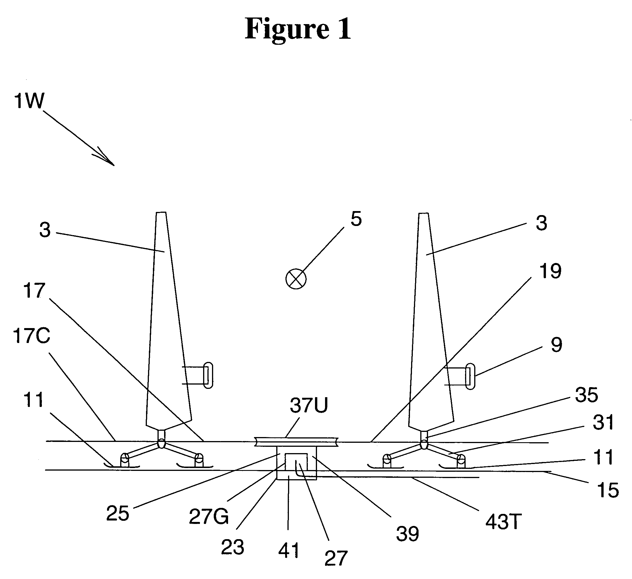
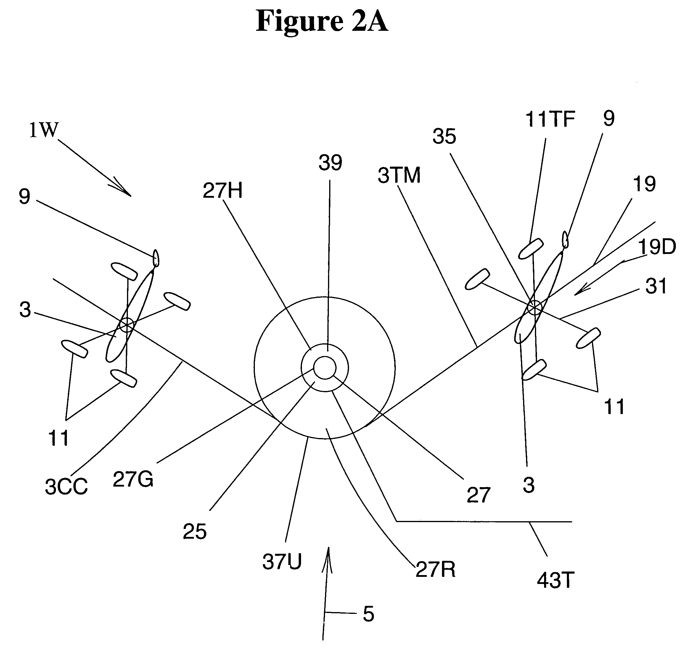
[0038]FIG. 1 shows a front view of a portion of a wind energy harvesting system 1W. This wind energy harvesting system includes plural runner-supported movable frames 31MF, each supported by support runner means 11 that slide along a frozen surface 15. The runner-supported movable frames 31MF include connecting structure 31 structurally connecting multiple runners. The runner-supported movable frames 31MF each support fluid-foil means 3 for contacting proximate flow fields of an air current 5 when said air current exists and carries wind energy in the form of fluid-dynamic kinetic energy, which fluid-foil means 3 are wings 3W in the illustrated embodiment. The runner-supported movable frames 31MF each support fluid-foil means 3 through fluid-foil base members 35. Thu...


PUM


Abstract

The invention provides an environmentally friendly renewable energy harvesting system for harvesting wind energy on a frozen surface, as in cold weather climatic regions associated with higher latitudes or higher altitudes, with snow or ice surfaces. A plurality of ski, skate or runner supported wings or sails are connected together to form a wind energy harvesting system, and capture wind energy by appropriate setting of wing or sail angles of attack so as to drive a cyclic motion that in turn can drive energy capture means such as electric generator means. The invention thus provides a wind energy harvesting system which is supported by a frozen surface, which includes fluid-foil means for interfacing with an air current such as a wind and which includes energy harvesting means utilizing periodic motion of the fluid-foil means for capturing wind energy and converting it into usable energy in a desired form such as electricity. The present invention is intended to provide devices, methods and systems for harvesting renewable energy which can be efficient and cost-effective for small-scale, medium-scale and large-scale applications, to provide real and substantial benefits to meet local energy needs while also more broadly serving humanity and our global environment.

Description

CROSS-REFERENCE TO RELATED PATENT APPLICATIONS[0001]This patent application entitled “WIND ENERGY HARVESTING SYSTEM ON A FROZEN SURFACE” is being filed simultaneously with the related patent application entitled “FLUID-DYNAMIC RENEWABLE ENERGY HARVESTING SYSTEM” also invented by Mithra M. K. V. Sankrithi and hereby incorporated herein by reference.BACKGROUND OF THE INVENTION[0002]As the World's human population grows and as the economic prosperity of that population grows, the energy demand of that population also grows. With limited availability of oil reserves, there is a growing need for the conception, development and deployment of cost-effective and large-scale renewable energy alternatives. The continued use of fossil fuels to meet current and emerging energy needs also has very negative environmental consequences, including massive emissions of pollutants and exacerbation of global warming and climate change. This provides further strong motivation for cost-effective, large-s...

Claims


Application Information

Patent Timeline
Patent Type & Authority Patents(United States)
IPC IPC(8): F03D9/00H02P9/04F03B13/00F03B13/10
CPCF03D3/067F03D5/02F05B2240/311Y02E10/74F05B2240/93Y02E10/70F05B2240/90
Inventor SANKRITHI, MITHRA M. K. V.
Owner RIC ENTERPRISES
Why Eureka
Try Eureka