
Apparatus, method, and system for dynamically selecting power down level

a technology of power down level and power down, applied in the direction of liquid/fluent solid measurement, instruments, sustainable buildings, etc., can solve the problem of power down level affecting exit latency and achieve the effect of less power

Active Publication Date: 2010-05-11
NVIDIA CORP
View PDF4 Cites 67 Cited by
  • Summary
  • Abstract
  • Description
  • Claims
  • Application Information

AI Technical Summary

Benefits of technology

[0006]Electronic systems often include power down levels that utilize less power than a normal operational mode. The depth of the power down levels affects exit latency. Electronic systems are conventionally designed to utilize a power down level consistent with a worst case latency. In accordance with one aspect of the present invention, the power down level for a system is dynamically selected based on the actual current latency tolerances of different active clients. One embodiment of a method of managing power down levels includes monitoring latency tolerances of a plurality of clients associated with client performance states. A minimum power down level capable of supporting a system latency associated with the plurality of clients is dynamically selected.

Problems solved by technology

The depth of the power down levels affects exit latency.

Method used


Image

  • Apparatus, method, and system for dynamically selecting power down level
  • Apparatus, method, and system for dynamically selecting power down level
  • Apparatus, method, and system for dynamically selecting power down level

Examples


Embodiment Construction

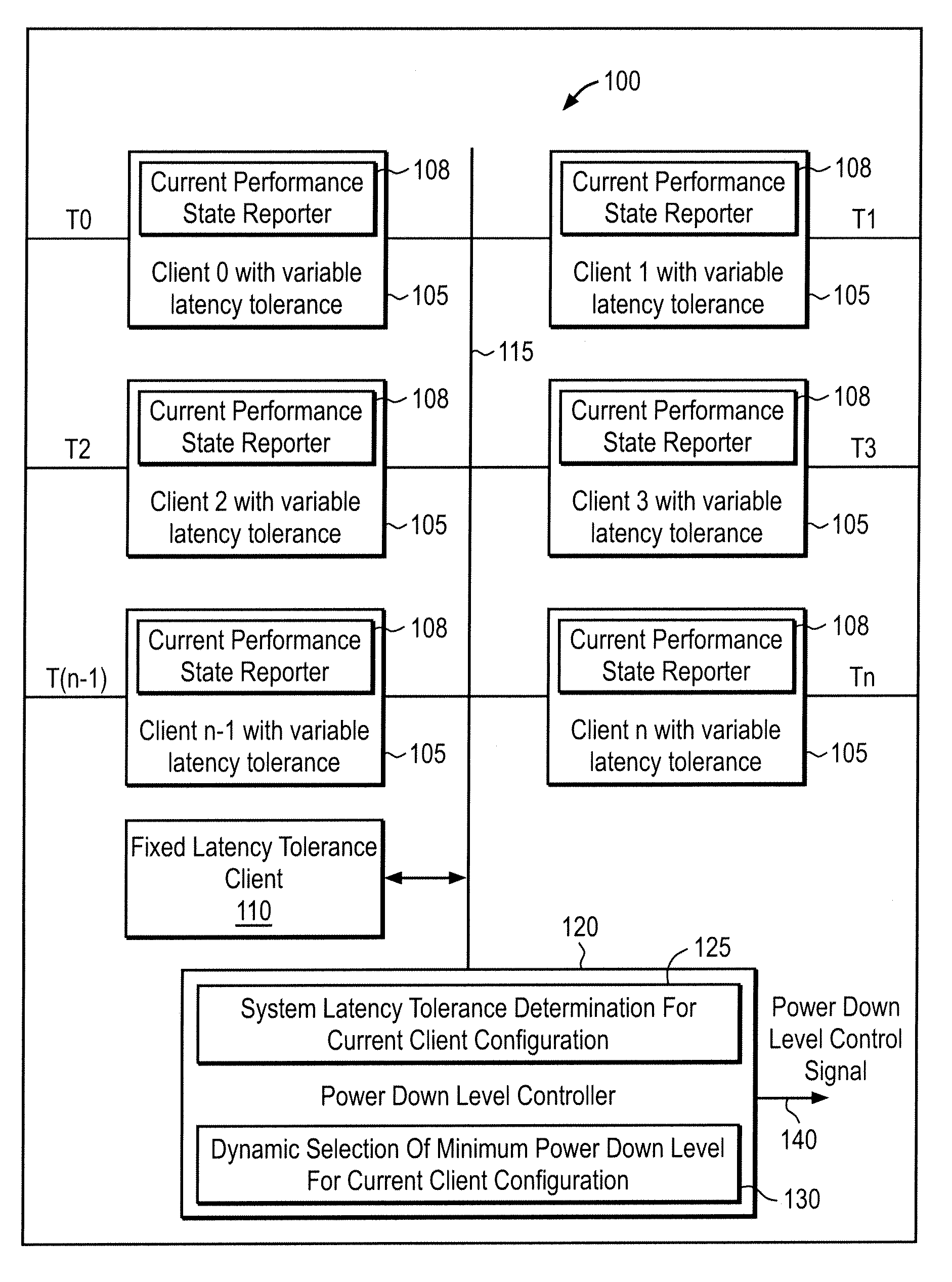
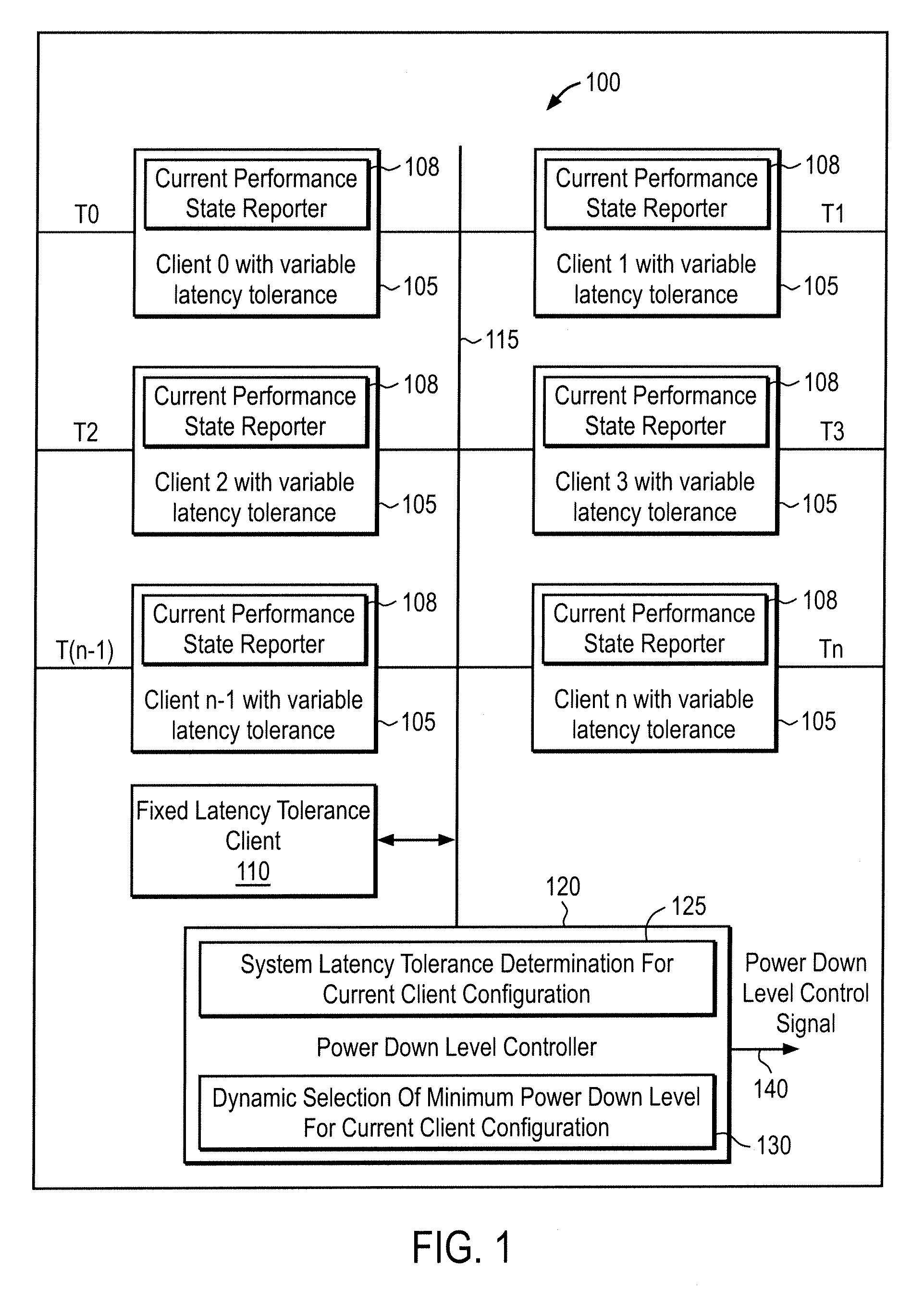
[0013]FIG. 1 illustrates an exemplary apparatus 100 in accordance with one embodiment of the present invention. Apparatus 100 may, for example, be implemented as an integrated circuit for use with a central processing unit (not shown in FIG. 1) and a memory (not shown in FIG. 1). A plurality of clients 105 are included where each client 105 manages a function. An individual client 105 may, for example, be a data consumer that acts as an agent or bus master related to a specific functional block of an integrated circuit.

[0014]Apparatus 100 is designed for use with a system having a plurality of system performance levels including a normal operating level that is high performance / high power consumption performance level and a plurality of other performance levels corresponding to power down levels with reduced power consumption. These system performance levels may be described as an active state, and LPS1, LPS2, and LPS3 Low Power states, where the higher numbered LPS states have a lo...


PUM


Abstract

A system has a plurality of different clients. Each client generates a report signal indicative of a current latency tolerance associated with a performance state. A controller dynamically determines a power down level having a minimum power consumption capable of supporting the system latency of the configuration state of the clients.

Description

FIELD OF THE INVENTION[0001]The present invention is general related to techniques for implementing a power savings mode in which one or more units are placed in a power down level.BACKGROUND OF THE INVENTION[0002]Many electronic systems have low power states, sometimes known as “sleep” states or “off states” although more generally there is now a spectrum of power down levels with reduced power level in addition to a “normal” operating state. For example, modern computer systems and graphics systems typically place different units and interfaces into a low power down state when specific units and interfaces are idle. For example, a microprocessor may have power states C0-C3, where C0 is the operating state, C1 is a halt state, C2 is stop-clock state, and C3 is sleep state. Some microprocessors also have deep sleep (C4) and / or deeper sleep states that differ in how long it takes to wake up the processor. Some buses, such as the HyperTransport (HT) bus facilitate power management suc...

Claims


Application Information

Patent Timeline
Patent Type & Authority Patents(United States)
IPC IPC(8): G06F1/26
CPCG06F1/3203G06F1/3287Y02B60/1282Y02B60/1278Y02D10/00
Inventor SURGUTCHIK, ROMANCHAPMAN, ROBERT WILLIAMRIEGELSBERGER, EDWARD L.SIMERAL, BRAD W.GYUGYI, PAUL J.
Owner NVIDIA CORP
Features
  • Generate Ideas
  • Intellectual Property
  • Life Sciences
  • Materials
  • Tech Scout
  • Unparalleled Data Quality
  • Higher Quality Content
  • 60% Fewer Hallucinations
Learn More