Engine exhaust gas purification device

a technology for exhaust gas purification and engine, which is applied in the direction of machines/engines, electrical control, separation processes, etc., can solve the problems of clogging of filter c, exhaust pressure rise, and inability to regenerate, so as to reduce the amount of new intake air, reduce the temperature of catalyst and/or filter, and reduce the effect of negative pressure inside the cylinder

Inactive Publication Date: 2010-05-18
ISUZU MOTORS LTD
View PDF25 Cites 15 Cited by
  • Summary
  • Abstract
  • Description
  • Claims
  • Application Information

AI Technical Summary

Benefits of technology

[0012]An object of the present invention is to provide an engine exhaust gas purification device which prevents unburned fuel components from accumulating in an EGR passage by scavenging the EGR passage as needed.
[0015]During regeneration of the filter, the control means may control an intake throttle valve provided in an intake passage of the engine to close. In so doing, the amount of new intake air is reduced during regeneration of the filter, and hence reductions in the temperature of the exhaust gas are suppressed, reductions in the temperature of the catalyst and / or the filter are suppressed, and a consequent deterioration in the regeneration capability of the filter is prevented.
[0017]According to this invention, if fuel ceases to be injected from the injector due to a speed reduction request or the like issued while fuel injection from the injector is being controlled such that unburned fuel components are supplied to the catalyst to regenerate the filter, the intake throttle valve is controlled to close, thereby reducing the amount of new intake air such that reductions in the temperature of the catalyst and / or the filter are suppressed. Furthermore, the EGR valve is controlled to open at the same time as the intake throttle valve is controlled to close, and hence negative pressure inside the cylinder, which is generated when the intake throttle valve is controlled to close, is reduced by controlling the EGR valve to open. As a result, oil loss via the piston rings and oil loss via the guides can be suppressed. Moreover, by controlling the EGR valve to open, residual unburned components in the EGR passage are scavenged by air.

Problems solved by technology

However, when the exhaust gas temperature is low, for example under low speed, low load conditions, the PM trapped in the filter c cannot be burned by the temperature of the exhaust gas, and hence regeneration is not possible.
As a result, the PM continues to accumulate in the filter c, causing the filter c to become clogged and the exhaust pressure to rise.
In the worst case, this may lead to blockages.

Method used


Image

  • Engine exhaust gas purification device
  • Engine exhaust gas purification device
  • Engine exhaust gas purification device

Examples


Embodiment Construction

[0020]A preferred embodiment of the present invention will be described below in detail on the basis of the attached drawings.

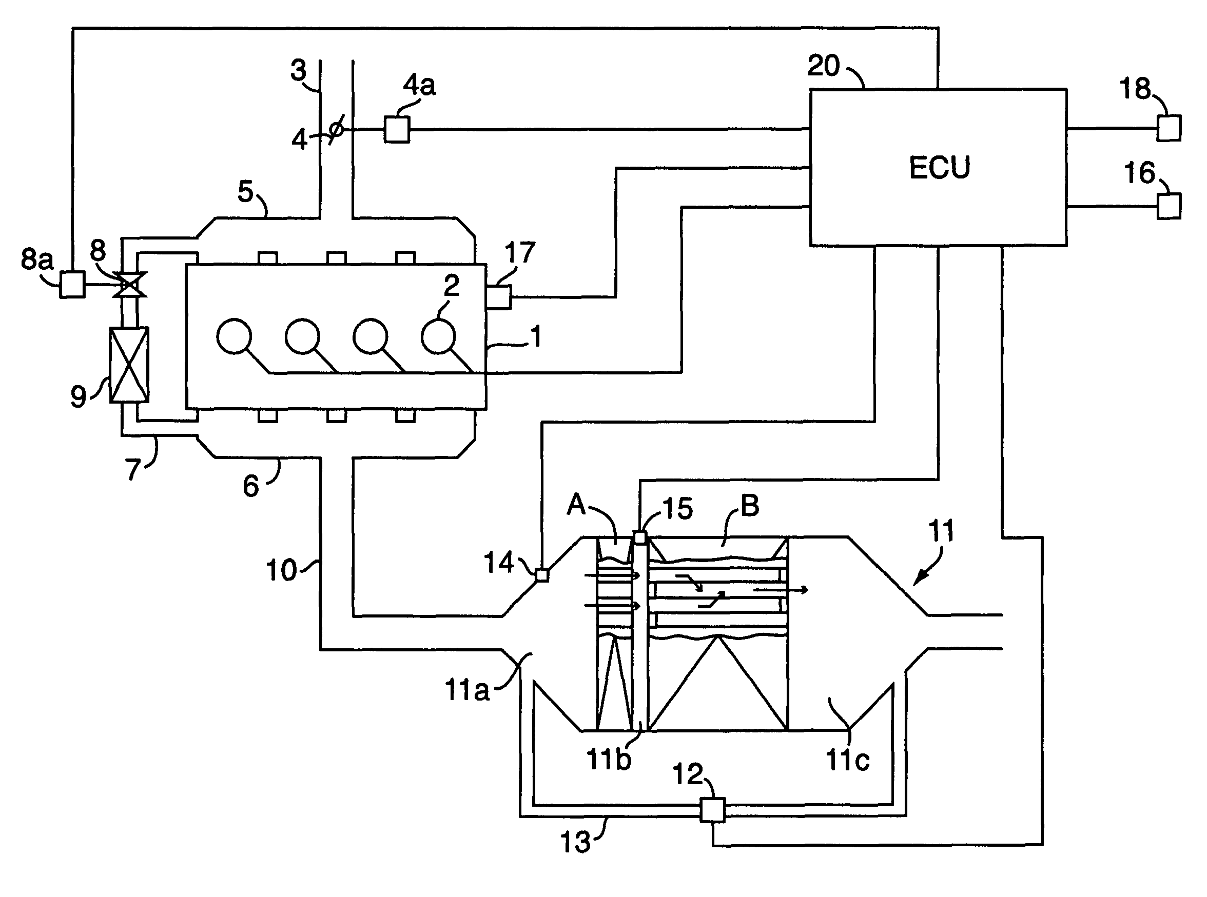
[0021]As shown in FIG. 1, an injector 2 (in the illustrated example, an injector of a common rail-type fuel injection system) is attached to a cylinder head of a diesel engine 1 installed in a vehicle. The injector 2 receives signals from an engine control unit (ECU) 20 serving as control means to control the injection timing and injection amount.

[0022]An intake throttle valve 4 is provided in an intake passage 3 of the engine 1 for varying the passage cross section. A driving portion 4a of the intake throttle valve 4 receives signals from the ECU 20 to open / close control the intake throttle valve 4.

[0023]An intake manifold 5 and an exhaust manifold 6 of the engine 1 are linked by an EGR passage 7. An EGR valve 8 is provided in the EGR passage 7 for varying the passage cross section. A driving portion 8a of the EGR valve 8 receives signals from the ECU 20 to ...


PUM

PropertyMeasurementUnit
temperatureaaaaaaaaaa
speedaaaaaaaaaa

Abstract

The present invention provides an engine exhaust gas purification device comprising a filter B provided in an exhaust passage (10) of an engine (1) for trapping particulate matter contained in the exhaust gas, a catalyst A for regenerating the filter B by burning the particulate matter trapped in the filter B, an EGR valve (8) provided in an EGR passage (7) linking the intake side and exhaust side of the engine 1, an injector (2) for injecting fuel into a cylinder, and control unit (20) for controlling the injector (2) and EGR valve (8). During regeneration of the filter B, the control unit (20) close the EGR valve (8) when fuel injection from the injector (2) is controlled to supply unburned fuel components to the catalyst A, and open the EGR valve (8) when no fuel is injected from the injector (2) upon a request for speed reduction or the like. In so doing, residual unburned fuel components in the EGR passage (7) are scavenged by air.

Description

CROSS REFERENCE TO RELATED APPLICATION[0001]The applicants hereby claim foreign priority benefits under U.S.C. §119 of Japanese Patent Application No. 2004-115815 filed on Apr. 9, 2004, and the content of which is herein incorporated by reference.BACKGROUND OF THE INVENTION[0002]1. Field of the Invention[0003]The present invention relates to an exhaust gas purification device for an engine, and more particularly to an engine exhaust gas purification device comprising a filter for trapping particulate matter contained in the exhaust gas, and an EGR (exhaust gas recirculation) valve for recirculating the exhaust gas to an intake side.[0004]2. Description of the Related Art[0005]Restrictions on the exhaust gas of diesel engines become stricter year by year, and hence the discharge amount of particulate matter (PM) contained in the exhaust gas must be suppressed. A continuous regeneration diesel particulate filter (DPF) exists as a device for removing PM from exhaust gas.[0006]As shown ...

Claims


Application Information

Patent Timeline
Patent Type & Authority Patents(United States)
IPC IPC(8): F01N3/00F02M25/07B01D46/42B01D53/94F01N3/02F02D9/02F02D21/08F02D41/00F02D41/02F02D41/12F02D41/38F02D41/40F02D43/00F02D45/00
CPCF02D41/005F02D41/029F02M25/0701F02M25/0727F02M25/0742F02D41/123F02D41/402F02D41/405Y02T10/47F02M25/0718F02D2200/0812F02M26/15F02M26/23F02M26/36F02M26/50Y02T10/40
Inventor ONODERA, TAKAOWU, WEIHASEYAMA, TAKASHIIWASHITA, TAKUROMATSUNUMA, ATSUSHIIKEDA, SHIGERUMIYAZAKI, TOSHIO
Owner ISUZU MOTORS LTD
Why Eureka
Try Eureka