Rearview mirror assembly with running lights

a rearview mirror and running light technology, applied in the direction of optical viewing, vehicle components, display means, etc., can solve the problem that the second vehicle adjacent to the first vehicle may not be able to adequately view the turn signal

Inactive Publication Date: 2010-05-18
BELL ALAN
View PDF18 Cites 32 Cited by
  • Summary
  • Abstract
  • Description
  • Claims
  • Application Information

AI Technical Summary

Benefits of technology

[0010]It is another object of the invention to provide an exterior rearview mirror for motorized vehicles that includes a plurality of illuminated multidimensional graphical images that can provide additional functionality.

Problems solved by technology

In many instances a driver in a second vehicle adjacent a first vehicle may not be able to adequately view the turn signals of the first vehicle due to his relative position to the front or rear of the first mentioned vehicle.

Method used


Image

  • Rearview mirror assembly with running lights
  • Rearview mirror assembly with running lights
  • Rearview mirror assembly with running lights

Examples


Embodiment Construction

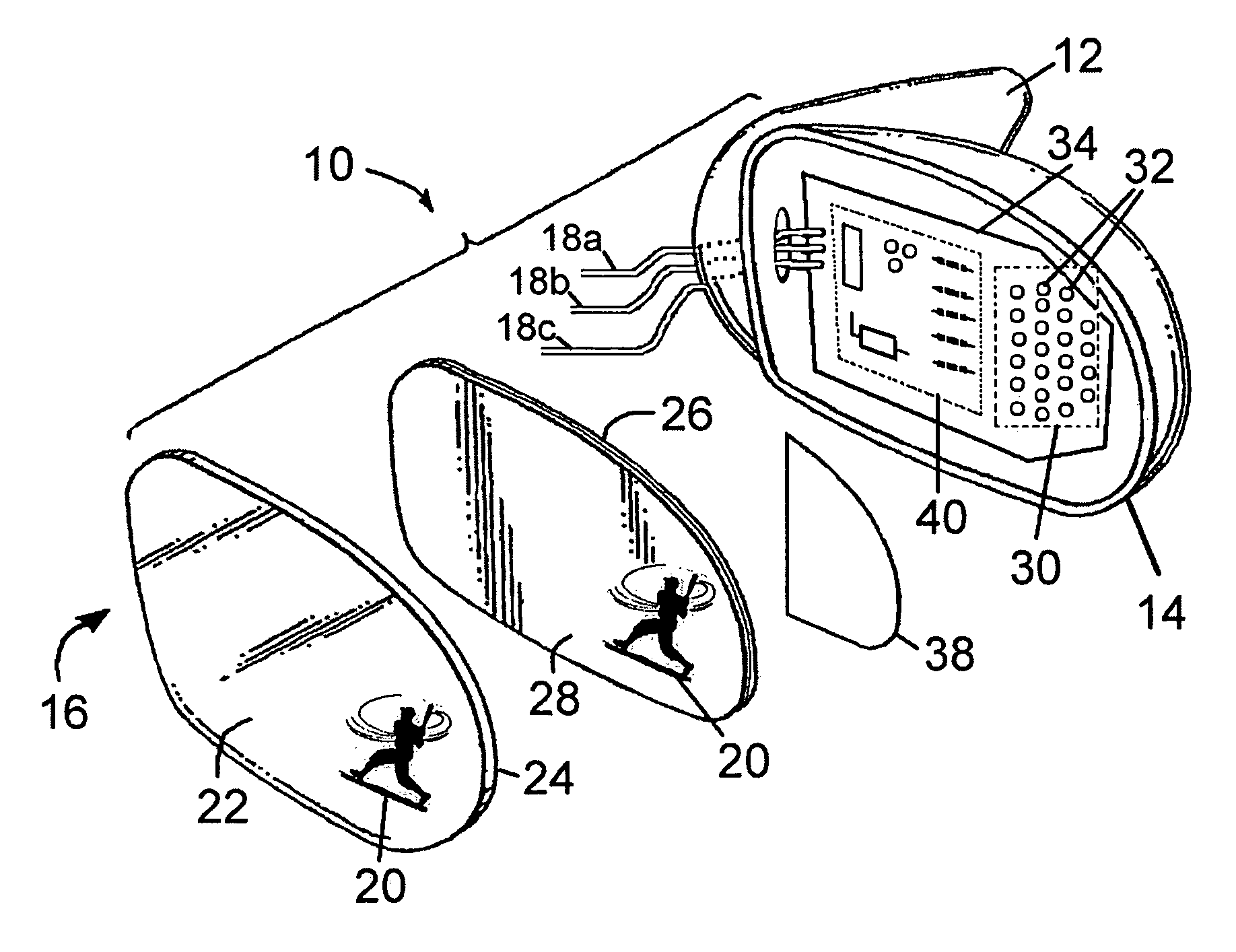
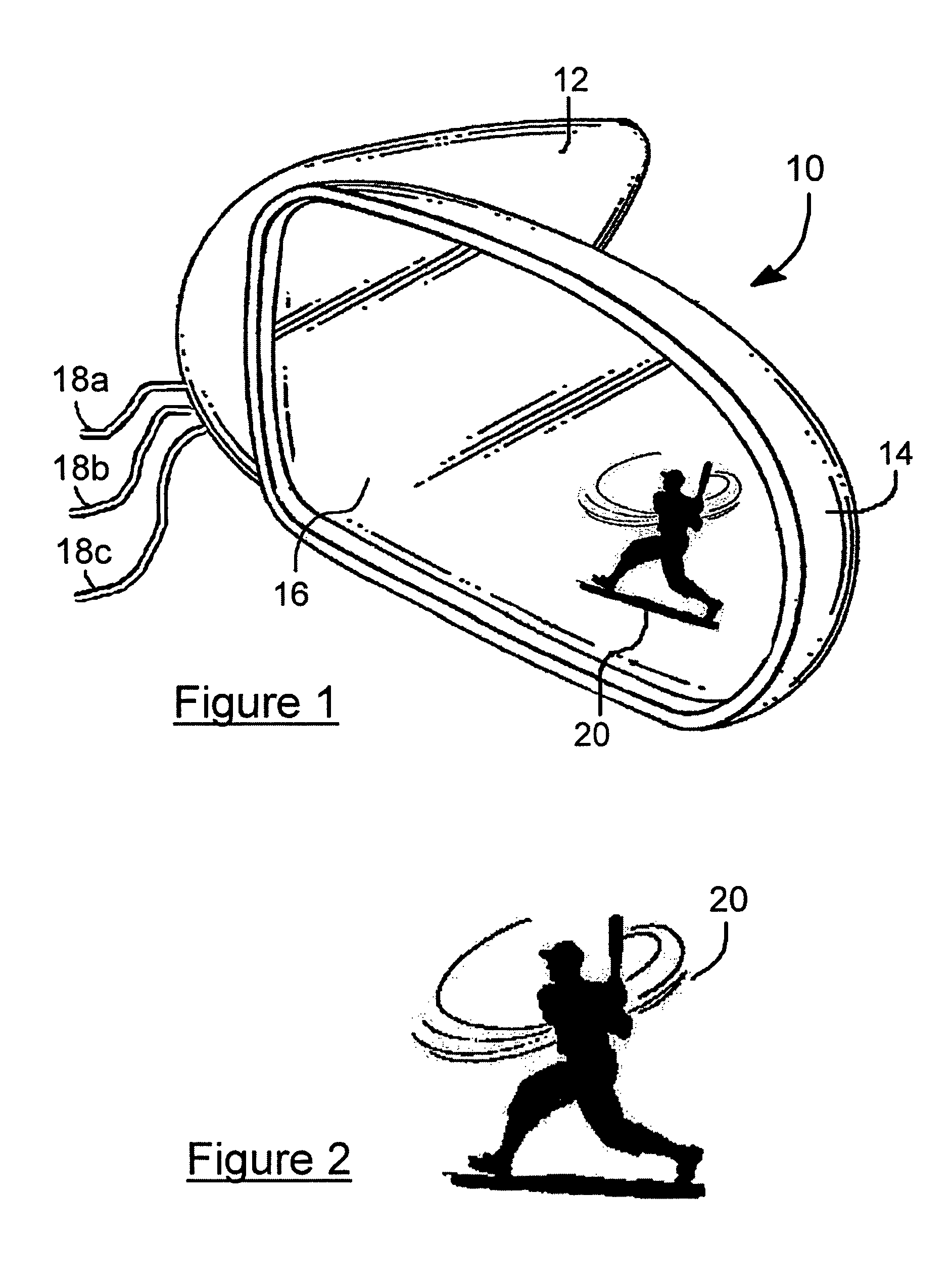
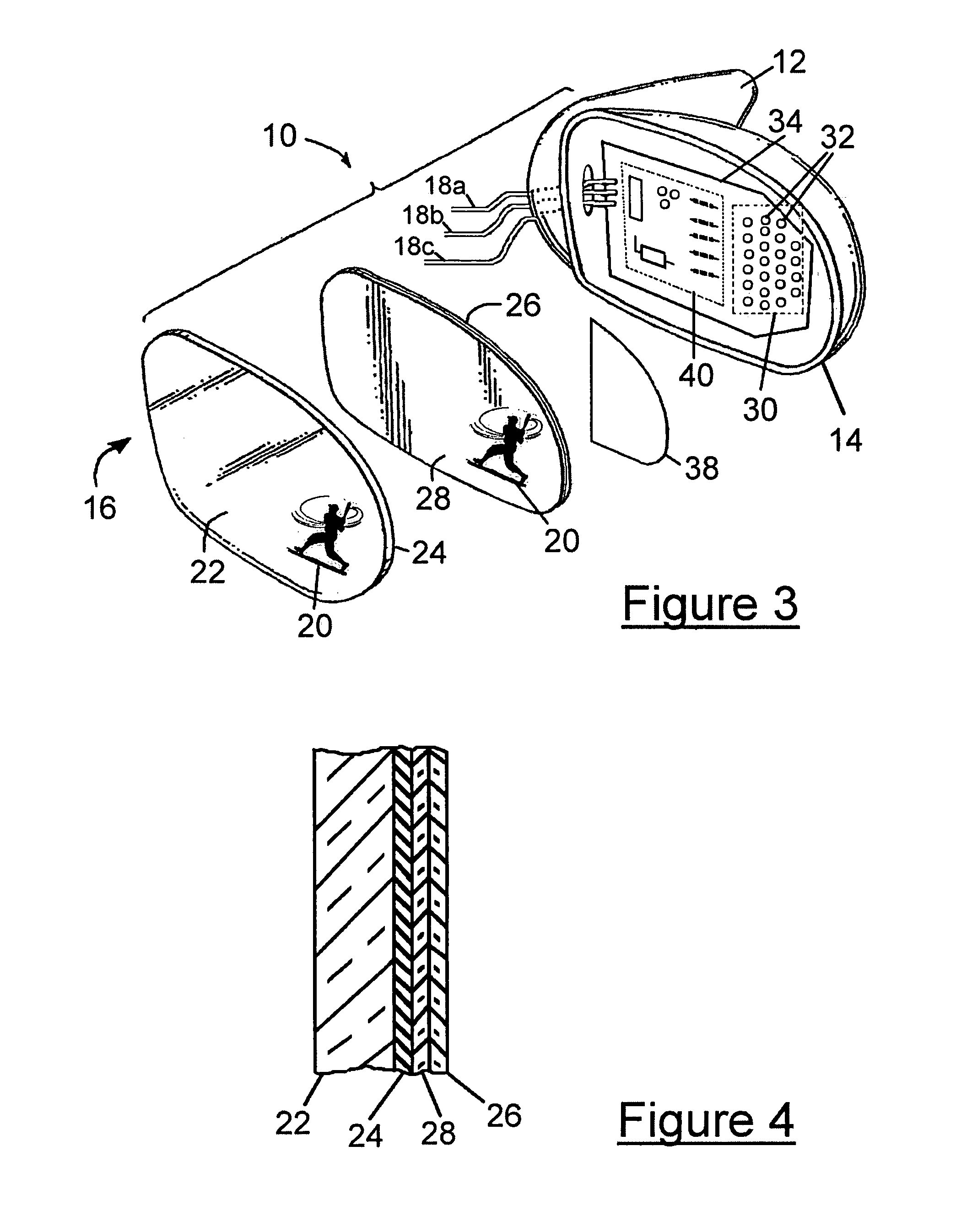
[0028]Generally speaking, the present invention provides a family of rearview mirror assemblies intended to be mounted to a motorized vehicle such as but not limited to an automobile, a truck, a motorcycle or a snowmobile. Each assembly includes a housing and a mirror mounted to the housing. At least one multidimensional graphical image is etched through the reflective layer, which preferably is located on the inner surface of the transparent substrate of the mirror. At least one light source illuminates the etched graphical image. The light source preferably is diffused and is implemented as a plurality of light emitting diodes (LEDs) attached to a printed circuit board (PCB) along with any necessary electronic circuitry.

[0029]Referring first to FIG. 1, there is shown a front elevational view of an exterior rearview mirror assembly 10 for mounting to a motorized vehicle (not shown) in accordance with one embodiment of the present invention. Exterior rearview mirror assembly 10 is m...


PUM


Abstract

A family of rearview mirror assemblies for motorized vehicles. Each assembly includes a housing, a mirror with at least one multidimensional graphical image etched through the reflective layer and illuminated by light sources such as LEDs located within the housing and behind the graphical image(s). The mirror assemblies operate properly with or without an external flashing circuit. The light source is energized at a first light level during normal operation of the vehicle to function as running lights, decorative lighting or accent lighting. When the light source is operated at a second light level (either higher or lower), the lighted graphical images may also provide additional functionality. The exterior rearview mirror assembly may optionally include additional light sources, light from which is viewable outside of the outer surface of the housing.

Description

FIELD OF THE INVENTION[0001]The present invention relates to backlit etched mirror technology and, more particularly, to backlit rearview mirrors for motorized vehicles that use the backlit multidimensional graphical images primarily as running lights.BACKGROUND OF THE INVENTION[0002]One or a pair of exterior rearview mirrors have been used on the sides of motorized vehicles such as motorcycles, trucks and automobiles for many years. The primary purpose of the mirrors was to provide the driver of the vehicle with information about other vehicles behind and on the side of his own vehicle.[0003]Vehicles are required to include such indicators as brake lights, turn signals and hazard indicators. Turn signals, however, are commonly mounted only on the very front and rear portions of the vehicle. In many instances a driver in a second vehicle adjacent a first vehicle may not be able to adequately view the turn signals of the first vehicle due to his relative position to the front or rear...

Claims


Application Information

Patent Timeline
Patent Type & Authority Patents(United States)
IPC IPC(8): B60Q1/26B60Q1/00
CPCB60R1/1207B60Q1/2665Y10S362/80B60Q1/381
Inventor BELL, ALAN
Owner BELL ALAN
Why Eureka
Try Eureka