Radio communication device and route search method

a radio communication device and route search technology, applied in the field of radio communication devices and route discovery methods, can solve the problems of increasing the processing time of each radio communication device, reducing throughput, increasing the power consumption of all radio communication devices, etc., to avoid unnecessary route control messages, increase the overhead of route request messages, and prolong the time that the acquired route can be used.

Active Publication Date: 2010-05-18
APPLE INC
View PDF18 Cites 14 Cited by
  • Summary
  • Abstract
  • Description
  • Claims
  • Application Information

AI Technical Summary

Benefits of technology

[0009]An object of the invention is to provide a radio communication device and a route discovery method capable of obtaining an appropriate route easily in accordance with the operating state characteristics of radio communication devices such as battery remaining power, relay load, or type of data flow, without complicated calculation or increasing of the overhead for searching the route in the radio communication device.

Problems solved by technology

The ad hoc network is a system which enables communication using a multiple step connection via several radio communication devices when a radio communication device cannot communicate with the desired radio communication device directly, and a problem is what route the radio communication device should take to forward data to the destination radio communication device.
In this case, if the battery of the selected radio communication device is exhausted, the route becomes invalid and the route discovery procedure is performed in the ad hoc network again.
Accordingly, there are problems that power consumption of all radio communication devices increases, and that throughput decreases due to the overhead increase in the communication band caused by control messages.
Accordingly, there are problems that processing for each radio communication device increases and that the overhead increases because of signaling.

Method used


Image

  • Radio communication device and route search method
  • Radio communication device and route search method
  • Radio communication device and route search method

Examples


embodiment 1

[0091]FIG. 1 to FIG. 10 show one embodiment of a radio communication device and a route discovery method according to an embodiment 1 of the invention.

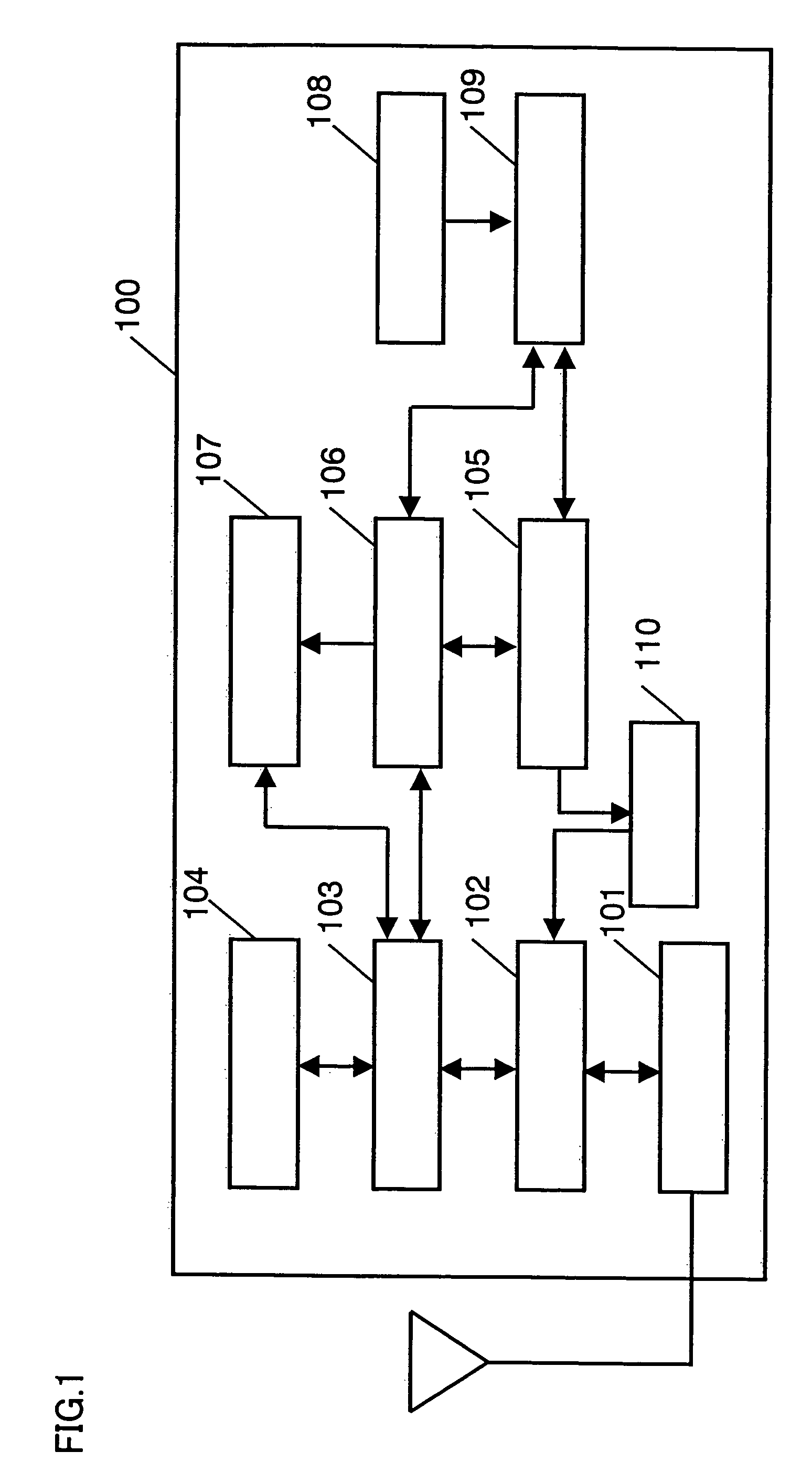
[0092]FIG. 1 is a block diagram showing a configuration of a radio communication device of the invention. A radio interface 101 includes an antenna, an RF circuit and a baseband processing circuit, which executes processing of modulating a signal received from a data link control unit 102, converting it into a radio signal and transmitting the signal from an antenna, and a processing of demodulating the radio signal from the antenna and giving the digital signal to the data link control unit 102.

[0093]In the data link control unit 102, framing a signal obtained from a network controller 103 in a format prescribed by a designated data link layer, giving the signal to the radio interface 101, removing data link layer header / tailer from the digital signal received from the radio interface 101, giving the signal to the network controller ...

embodiment 2

[0134]FIG. 12 to FIG. 16 show one embodiment of a radio communication device and a route discovery method according to an embodiment 2. FIG. 12 to FIG. 16 have the same fundamental configuration as the embodiment 1, and therefore the same reference numerals are given to the same components, explanations thereof are omitted, and only different components will be explained.

[0135]FIG. 12 is a block diagram showing a configuration of the radio communication device of the invention.

[0136]A route request message management unit 1201 has the function, explained in embodiment 1, of giving indexes for clearly distinguishing information stored therein, identifying a route request message from a specific source to a specific destination. FIG. 13 shows an example of a route request message table managed in the route request message management unit 1201.

[0137]A radio communication device having the route request message table shown in FIG. 13 has an entry showing that a route request message (th...

embodiment 3

[0156]FIG. 17 to FIG. 19 show a radio communication device and a route discovery method according to embodiment 3.

[0157]FIG. 17 is a block diagram showing a configuration of a radio communication device 1700 according to the embodiment. In FIG. 17, a neighborhood table management unit 1701, a route request message management unit 1702 and a network controller 1703 are different from the embodiment 1. Functions of these components will be explained as follows.

[0158]The neighborhood table management unit 1701 performs management for the neighborhood of the radio communication device, namely, radio communication devices in the area where the radio communication device can directly communicate with them, managing identifiers of these radio communication devices, receiving time of packets, flags showing validity / invalidity thereof and the total number of the radio communication devices. FIG. 18 shows an example of a neighborhood table in the neighborhood table management unit 1701.

[0159]...


PUM


Abstract

A radio communication device includes a reception unit for receiving a route request message from another radio communication device, a route control message processing unit for judging whether the received route request message is addressed to itself or not, a route request message management unit for deciding a delay amount for delaying response transmission or relay forwarding with regard to the route request message according to an operating state of the radio communication device when the route request message is not addressed to itself, and a delay processing unit which performs response transmission or relay forwarding to the route request message when the delay amount time has expired. Thus, a route selected giving preference to radio communication devices having a preferable operating state can be obtained.

Description

[0001]This application is a U.S. National Phase Application of PCT International Application PCT / JP2005 / 004497.TECHNICAL FIELD[0002]The invention relates to a radio communication device and a route discovery method in a radio ad hoc network system, more particularly, relates to a radio communication device and a route discovery method which searches an optimum route in the ad hoc network system.BACKGROUND ART[0003]With the diversity of radio communication devices possessed by users, it is becoming possible to send e-mail from radio communication devices, use the Internet and exchange data at offices, on street corners, in transport vehicles during movement, or the like. The existence of infrastructure is a prerequisite for these radio networks. On the other hand, an ad hoc network has begun to attract attention which does not require infrastructure, in which a radio communication device performs communication by constructing networks temporarily with radio communication devices scat...

Claims


Application Information

Patent Timeline
Patent Type & Authority Patents(United States)
IPC IPC(8): G08C15/00H04B7/00H04B7/26H04L12/28H04L12/701H04W16/26H04W40/02H04W40/10H04W40/14H04W40/34H04W74/08H04W84/12H04W84/18
CPCH04L45/02H04W40/24H04W40/02H04W84/18H04W40/10Y02D30/70
Inventor KOBAYASHI, HIROKAZUKAWAHARA, TOYOKIKANAZAWA, TAKESHIOKA, NAOTO
Owner APPLE INC
Why Eureka
Try Eureka