Methods and devices for performing procedures within the ear, nose, throat and paranasal sinuses

a technology of paranasal sinuses and methods, applied in the field of medical devices, can solve the problems of inability to mount sensors on the proximal portion of the surgical procedure, inability to move or remodel the bony structure, and inability to achieve precise positioning and movement. , to achieve the effect of facilitating natural drainage, avoiding undesirable trauma or damage, and facilitating precise positioning and movemen

Active Publication Date: 2010-05-18
ACCLARENT INC
View PDF218 Cites 414 Cited by
  • Summary
  • Abstract
  • Description
  • Claims
  • Application Information

AI Technical Summary

Benefits of technology

[0018]Further in accordance with the invention, there are provided sensor-equipped working devices (e.g., guidewires, catheters, cannula, tubes, dilators, balloons, substance injectors, needles, penetrators, cutters, debriders, microdebriders, hemostatic devices, cautery devices, cryosurgical devices, heaters, coolers, scopes, endoscopes, light guides, phototherapy devices, drills, rasps, saws, etc.) useable to perform image guided FTSI procedures or other image guided ENT procedures. These image guided working devices of the present invention generally comprise an elongate shaft that is insertable through the nose to a location within a paranasal sinus, ear, nose or throat of the subject and one or more sensor(s) is / are positioned on or in the device at a location that becomes inserted into the subject's body during the procedure. In some embodiments, a sensor may be located at the distal tip of the device. Additionally or alternatively, sensor(s) may be located at other locations on the shaft of the device, such as at the location of a particular working element (e.g., a dilator, balloon, substance injector, needle, penetrator, cutter, debrider, microdebrider, hemostatic device, cautery device, cryosurgical device, heater, cooler, scope, lense, port, endoscope, light guide, phototherapy device, drill, rasp, saw, etc.). In some embodiments, the shaft of the working device proximal to the sensor(s) may be flexible or malleable. Such flexibility or malleability may allow the working device to be advanced though tortuous regions of the intra nasal anatomy and / or to be positioned behind obstructive anatomical structure(s) (e.g., behind the uncinate process) without traumatizing or requiring removal or surgical modification of the obstructive anatomical structure(s).
[0019]Still further in accordance with the present invention, there is provided a system of working devices specifically useable to perform an image guided FTSI procedure. Such system generally comprises a flexible guidewire that is advanceable into the ostium of a paranasal sinus and a dilation catheter that is advanceable over the guidewire and useable to dilate the ostium of the paranasal sinus. A sensor is located on a portion of the guidewire and / or dilation catheter that becomes positioned within the subject's body. The sensor communicates with the image guidance system to provide real time indicia of the position of the guidewire and / or dilation catheter such that the operator may precisely position the dilator within the desired sinus ostium without the need for obtaining direct line-of-sight endoscopc view of that sinus ostium. Optionally, the system may additionally comprise a tubular guide through which the guidewire and / or dilation catheter may be advanced. The tubular guide may be rigid, flexible or malleable and may be specifically configured to be advanced through the nose to a position within or near the ostium of the affected paranasal sinus.
[0020]Still further in accordance with the present invention, there are provided fiducial marker devices that may be precisely and reproducibly positioned within the mouth of a human subject. In some embodiments, these fiducial marker devices may incorporate brackets, projection of other configurational attributes for mounting of a transmitter useable in conjunction with an electromagnetic image guidance system.

Problems solved by technology

In some cases, such dilation of the ostium may fracture, move or remodel bony structures that surround or are adjacent to the ostium.
Electromechanical systems have not been widely used in ENT or sinus surgery.
However, in the new FTSI procedures and other new ENT procedures that use flexible and / or malleable catheters and instruments, it is no longer suitable to mount the sensors on proximal portions of the surgical instruments such that the sensors remain outside of the body.

Method used


Image

  • Methods and devices for performing procedures within the ear, nose, throat and paranasal sinuses
  • Methods and devices for performing procedures within the ear, nose, throat and paranasal sinuses
  • Methods and devices for performing procedures within the ear, nose, throat and paranasal sinuses

Examples


Embodiment Construction

[0065]The following detailed description, the drawings and the above-set-forth Brief Description of the Drawings are intended to describe some, but not necessarily all, examples or embodiments of the invention. The contents of this detailed description, the accompanying drawings and the above-set-forth brief descriptions of the drawings do not limit the scope of the invention or the scope of the following claims, in any way.

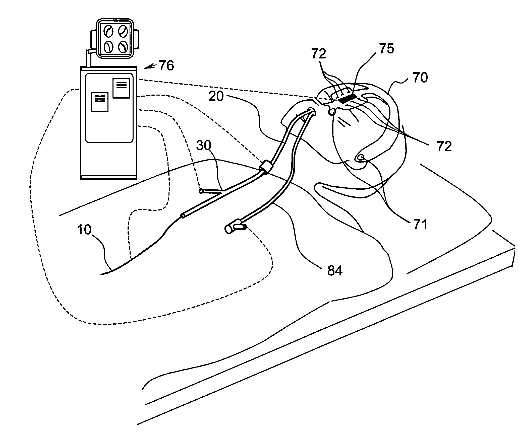
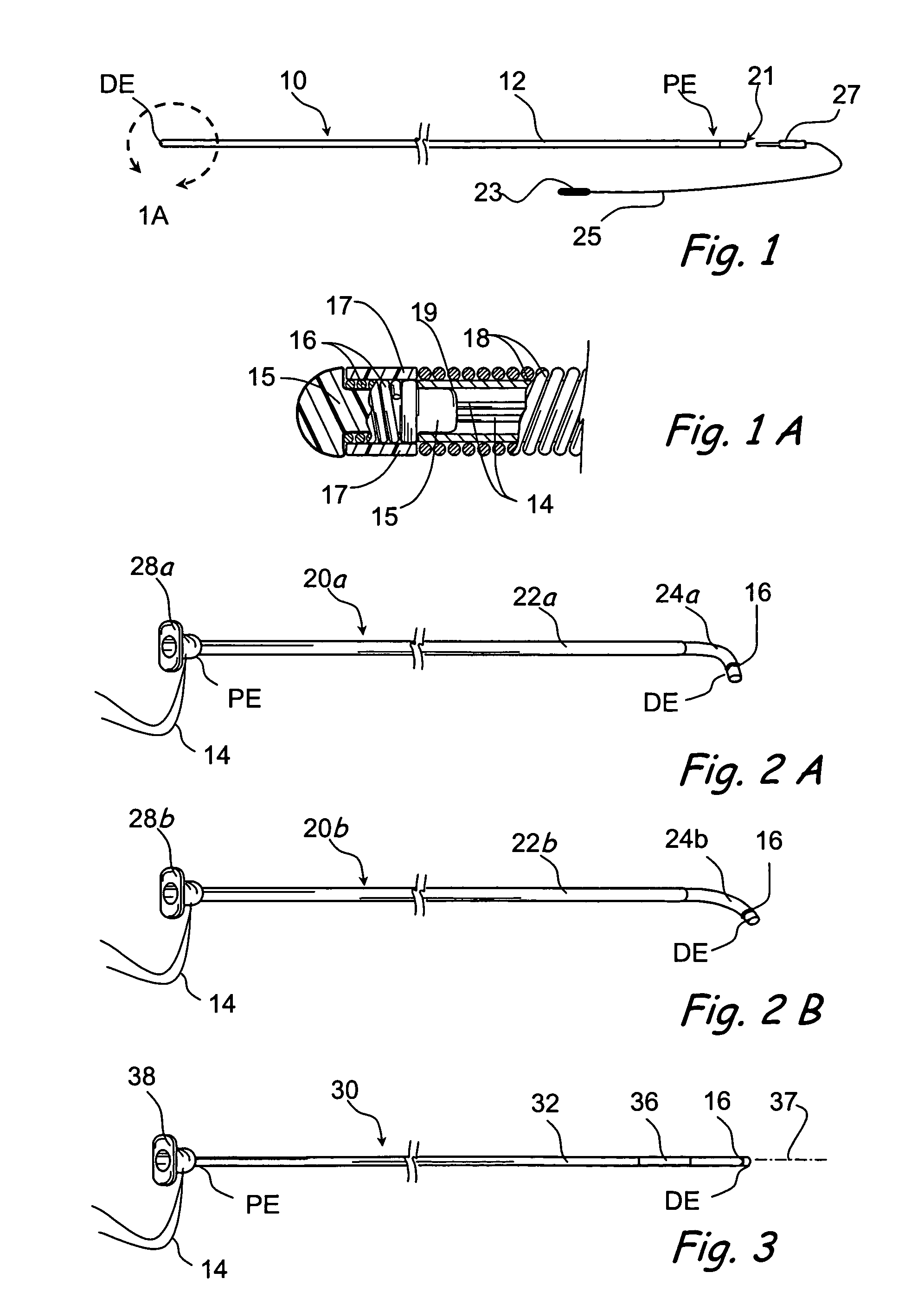
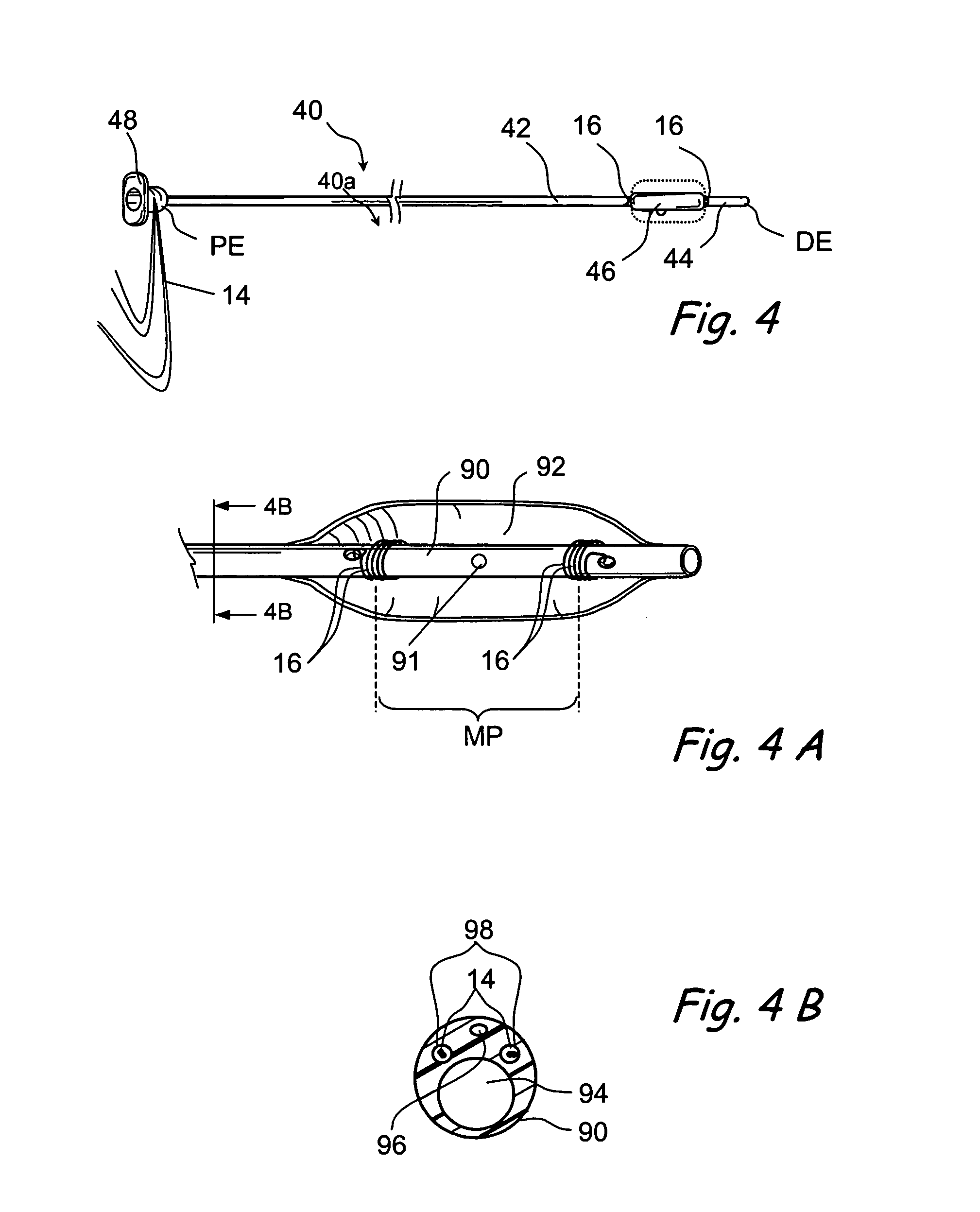
[0066]In this invention, various types of working devices are equipped with sensors and are used to perform interventional procedures within the paranasal sinuses, ears, noses and throats of human or animal subjects, while an image guidance system is used to track the location of the sensor(s) and, hence, the location(s) of the working device(s). FIGS. 1-6 and 11 show examples of sensor equipped working devices of the present invention. FIGS. 7A-17 show various components and operational aspects of an image guidance system of the present invention and its use in ...


PUM


Abstract

Devices, systems and methods for performing image guided interventional and surgical procedures, including various procedures to treat sinusitis and other disorders of the paranasal sinuses, ears, nose or throat.

Description

RELATED APPLICATION[0001]This application is a continuation-in-part of 1) U.S. patent application Ser. No. 10 / 829,917 entitled “Devices, Systems and Methods for Diagnosing and Treating Sinusitis and Other Disorders of the Ears, Nose and / or Throat” filed on Apr. 21, 2004, 2) U.S. patent application Ser. No. 10 / 912,578 entitled “Implantable Device and Methods for Delivering Drugs and Other Substances to Treat Sinusitis and Other Disorders” filed on Aug. 4, 2004, 3) U.S. patent application Ser. No. 10 / 944,270 entitled “Apparatus and Methods for Dilating and Modifying Ostia of Paranasal Sinuses and Other Intranasal or Paranasal Structures” filed on Sep. 17, 2004 and 4) U.S. patent application Ser. No. 11 / 037,548 entitled “Devices, Systems and Methods For Treating Disorders of the Ear, Nose and Throat” filed Jan. 18, 2005, the entireties of each such parent application being expressly incorporated herein by reference.FIELD OF THE INVENTION[0002]The present invention relates generally to ...

Claims


Application Information

Patent Timeline
Patent Type & Authority Patents(United States)
IPC IPC(8): A61B1/00A61B1/32A61B19/00A61F2/00A61F2/18A61F2/82A61F13/00A61K9/22A61M1/00A61M25/00A61M29/00
CPCA61B5/06A61B5/6851A61B19/5244A61B19/54A61M25/10A61B17/24A61B17/320725A61B17/320758A61B17/320783A61B17/3478A61B19/5212A61B2017/22061A61B2019/204A61B2019/505A61B2019/507A61B2019/5248A61B2019/5251A61B2019/5287A61B2019/5291A61B2019/5458A61B2019/5483A61F2/18A61F2/82A61F2250/0039A61M25/007A61M2025/0037A61M2025/004A61M2025/1052A61B2090/3983A61B90/16A61B2034/2048A61B2090/363A61B34/20A61B90/361A61B2034/105A61B2034/107A61B2034/2051A61B2090/365A61B90/39A61B2090/3958A61M2025/09108
Inventor CHANG, JOHN Y.MAKOWER, JOSHUAVRANY, JULIA D.MORRISS, JOHN H.MUNI, KETAN P.
Owner ACCLARENT INC
Why Eureka
Try Eureka