Resistance welded wire to hollow tubing joints and method

a technology of resistive welding and hollow tubing, which is applied in the direction of machine supports, child seats, manufacturing tools, etc., can solve the problems of long cycle times, unsatisfactory uniform welds, defects and rattles, and achieve the effect of reducing consumable costs and reducing long cycle times

Inactive Publication Date: 2010-05-25
L & P PROPERTY MANAGEMENT CO
View PDF6 Cites 10 Cited by
  • Summary
  • Abstract
  • Description
  • Claims
  • Application Information

AI Technical Summary

Benefits of technology

[0007]It is yet another object of the invention to produce uniform joining of wire formed parts to metal tubes with a bond that may be visually and mechanically inspected easily.
[0008]It is yet another object of the invention to provide a method of joining wire formed parts to hollow tubes that presents little risk of burn through of the parts, weld splatter, or weld slag.
[0009]It is a further object of the invention to decrease the long cycle times required for joining wire formed parts to metal tubes by spot welding and to decrease the consumable costs for such joinings.

Problems solved by technology

Traditionally, wire formed parts have either been welded to metal tubes or mounted in brackets welded to the metal tubes, however, the spot welding processes typically used have required relatively long cycle times, have not produced sufficiently uniform welds, and have resulted in defects and rattles because of weld splatter and weld slag.
Prior attempts to utilize resistance heating and upset forging techniques when joining wire forms to tubing have not been successful because the entire segment of wire passing through the hollow tube as well as the end portion extending from the tube have been heated to a plastic state.
Attempts to upset the portion of the wire extending through the tubing have generally resulted in simply creating a mass of metal within the tube.

Method used


Image

  • Resistance welded wire to hollow tubing joints and method
  • Resistance welded wire to hollow tubing joints and method
  • Resistance welded wire to hollow tubing joints and method

Examples


Embodiment Construction

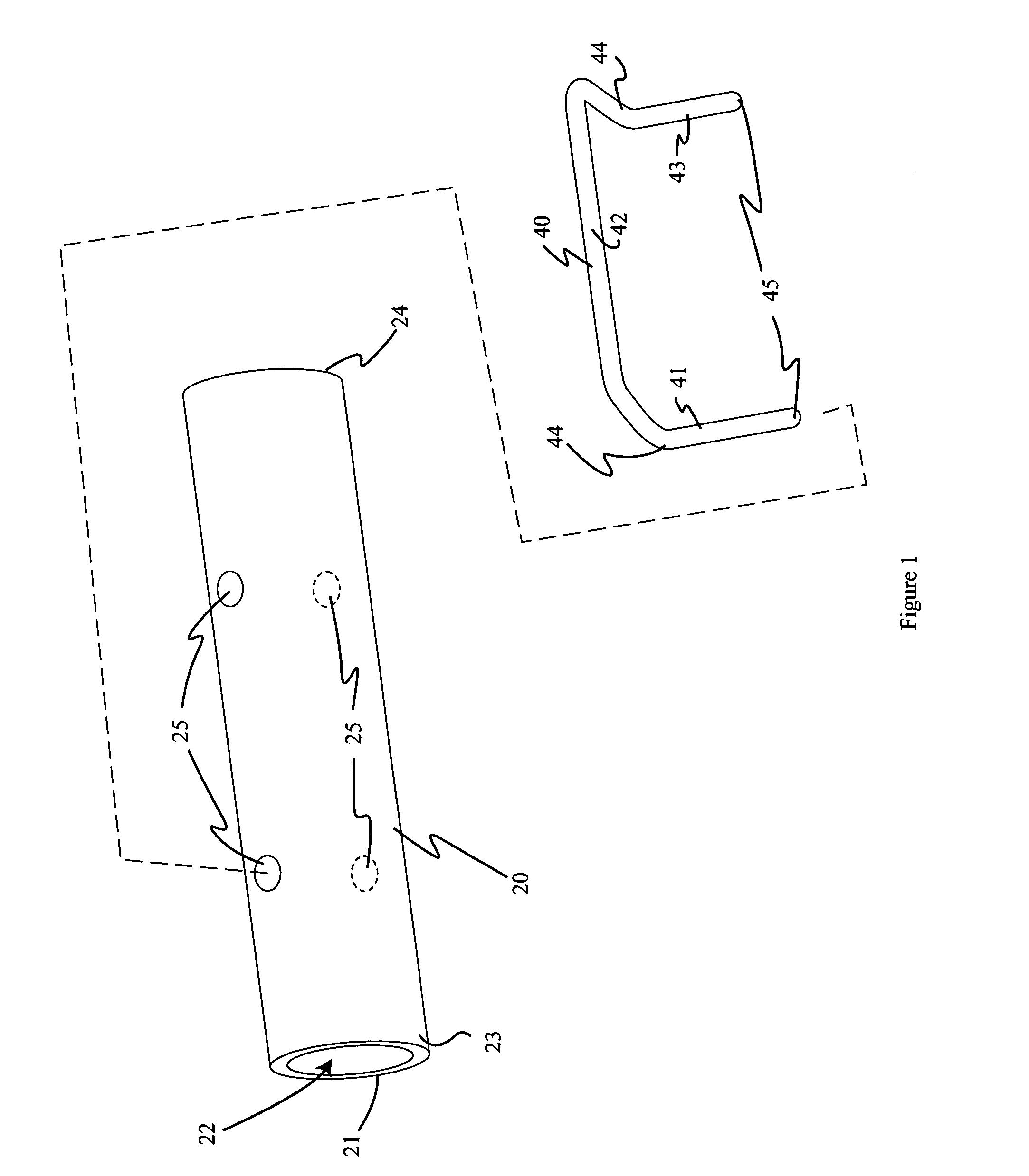
[0040]In FIG. 1, representative tube 20 and formed wire 40 are shown. Tube 20 is formed of a cylindrical wall 21 of metal defining lumen 22 and has a first end 23 and opposite second end 24. Openings 25 on the exterior surface of tube 20 define pathways that proceed substantially through the center point of the cross section of the tube to openings 25′ on the opposite tube wall. The work piece 40 has a central section 42 and a first leg section 41 and second leg section 43, each having an end 45. Between the legs 41, 43 and central portion 42 is typically a bend 44 in the wire form 40.

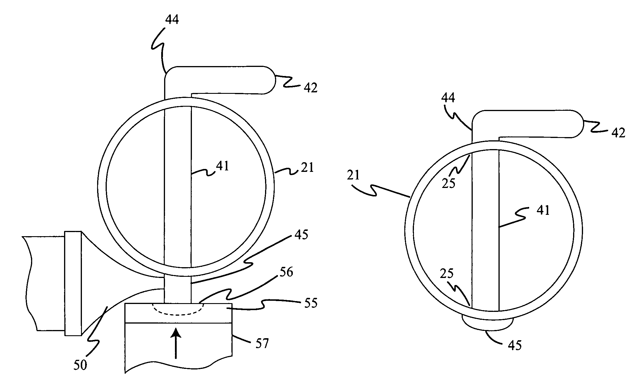
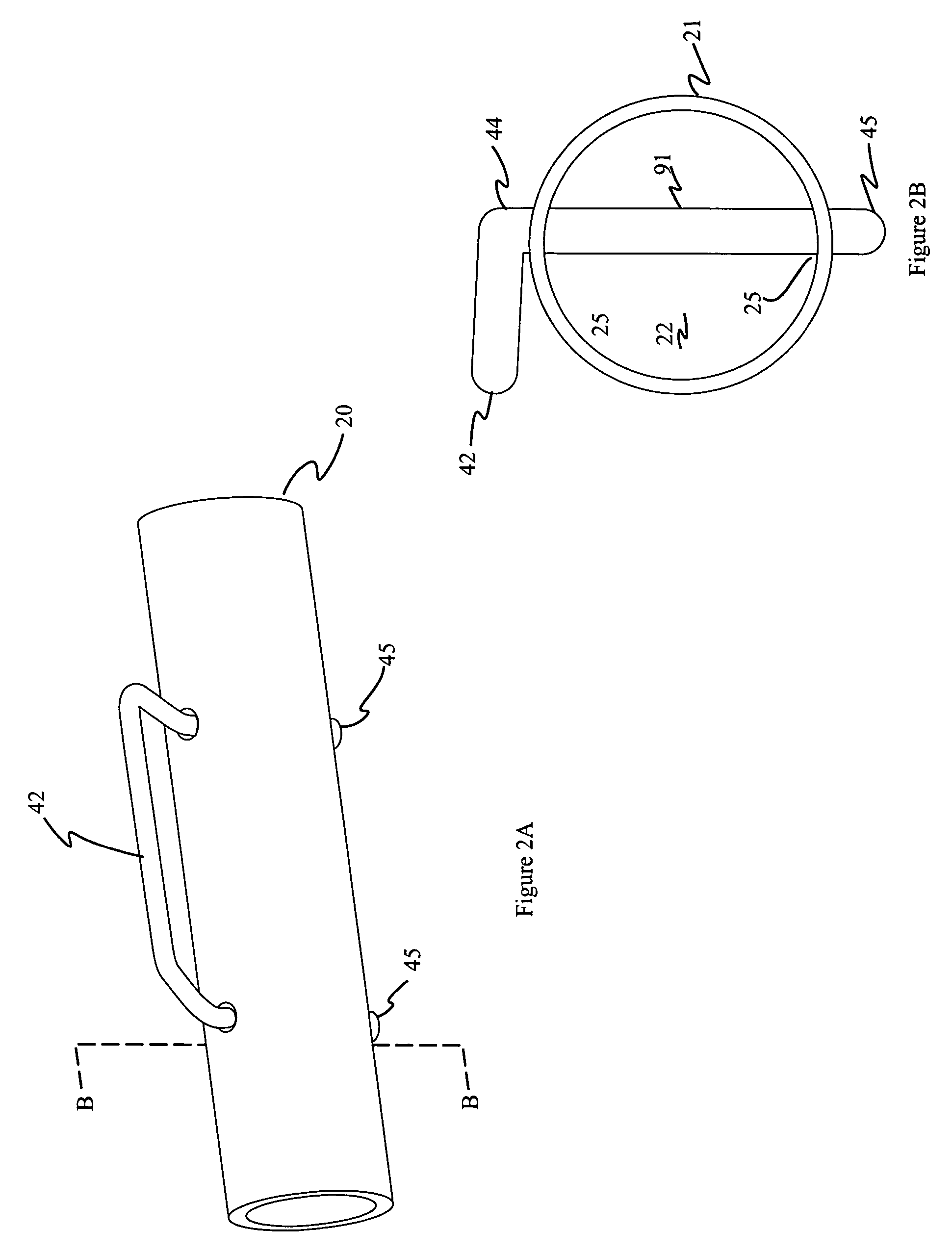
[0041]The formed wire 40 is shown with legs 41, 43 inserted through apertures 25, 25′ in FIG. 2A. The ends 45 of leg portions 41, 43 extend through the lumen 22 of the tube and out the opposite side of the tube wall 21 through openings 25′. FIG. 2B is a sectional view taken along line B-B of FIG. 2A and shows the first leg portion 41 extending substantially through the center of the lumen 22 and end 45...


PUM

PropertyMeasurementUnit
diametersaaaaaaaaaa
forcesaaaaaaaaaa
diameteraaaaaaaaaa

Abstract

Upset forging is utilized to join formed wire (40) to metal tubing (20). The ends (41) of formed wires (40) are passed completely across the width of the tube and heating electrodes (74) positioned only on the side of the tubing (20) from which the ends protrude and only the protruding ends (41) are heated to a plastic state. Back plates (30) are employed about the ends (41) to facilitate the upset forging process. An improved ISOFIX support is provided wherein a wire (40) is mounted across the width of a tube (20) and a bracket (30) placed over the wire (40) in contact with the tube (20) and these components are held together by upset forging the wire ends (41).

Description

CROSS REFERENCES TO RELATED APPLICATIONS[0001]This application claims priority to U.S. Application No. 60 / 538,338 filed on Jan. 22, 2004.FIELD OF THE INVENTION[0002]This invention is in the field of wire forming and joining, and especially the use of upset forging to join wire to hollow tubing.BACKGROUND OF THE INVENTION[0003]Wire forming manufacturing allows the rapid creation of custom parts by shaping wire feed stock often having diameters of about 0.25 inches, though wire forming is practiced over a wide range of wire diameters. When wire formed components are joined together, typically by spot welding, relatively strong and lightweight frames may be created. Wire formed structures have found widespread acceptance throughout the automotive industry due to the strength, weight, and resiliency of these parts.[0004]Joining wire formed components to flat metal parts has not presented substantial difficulties for the wire forming industry. The wire may in some cases be welded to the ...

Claims


Application Information

Patent Timeline
Patent Type & Authority Patents(United States)
IPC IPC(8): B21D39/00B21F5/00B21F15/04B21K25/00B23P11/00B60N2/28B60N2/68F16L3/08
CPCB21F5/00B21F15/04B21K25/00B60N2/682B60N2/2887Y10T29/49908Y10T29/49915
Inventor MCCAY, JEFFREY A.
Owner L & P PROPERTY MANAGEMENT CO
Why Eureka
Try Eureka