Arrangement and method for producing a camshaft

a camshaft and camshaft technology, applied in the direction of cams, cables for vehicles/pulleys, furnace components, etc., can solve the problems of superfluous expensive special machines, and achieve the effects of low investment costs, high availability, and simple handling

Inactive Publication Date: 2010-05-25
CAMTEC INT AG
View PDF10 Cites 10 Cited by
  • Summary
  • Abstract
  • Description
  • Claims
  • Application Information

AI Technical Summary

Benefits of technology

[0012]It is thus the object of the present invention to avoid the disadvantages of the known methods, especially to provide an arrangement and a method of the type described initially which is distinguished by simple handling and low investment costs. The arrangement should further have a high availability and should also thus ensure a high mounting accuracy of the cams for the camshaft. The method should further be simplified in such a manner that no specialist staff are required in the event of faults and changeover times can be kept short.

Problems solved by technology

As a result of this arrangement, it is achieved that expensive special machines are superfluous and largely standard or series-produced machines must be acquired as machining stations.

Method used


Image

  • Arrangement and method for producing a camshaft
  • Arrangement and method for producing a camshaft
  • Arrangement and method for producing a camshaft

Examples


Embodiment Construction

[0055]The figures show exemplary embodiments with the features of the invention in a schematic representation; they do not present any exact size relationships (or dimensional details) and merely serve to illustrate the basic principle.

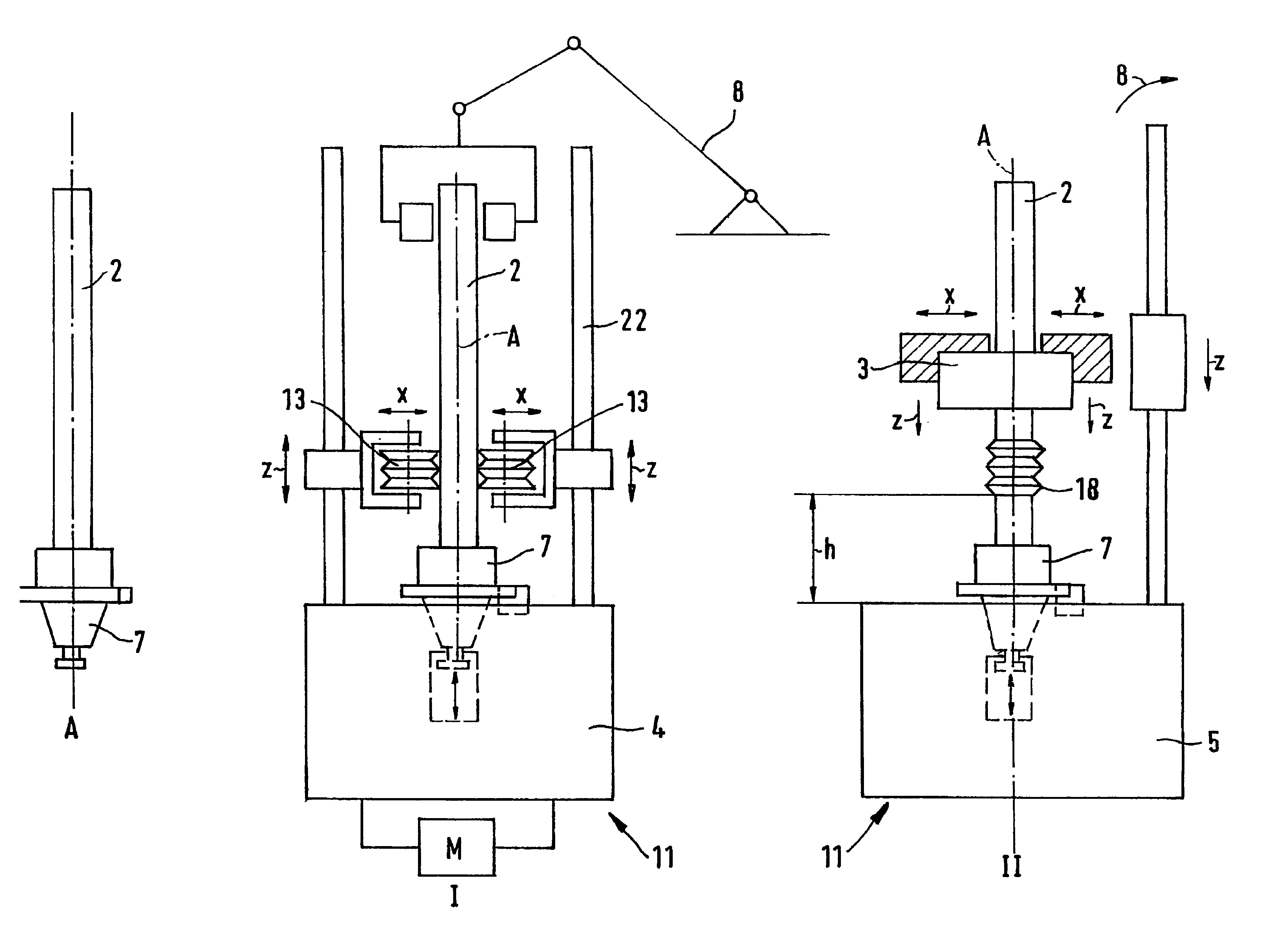
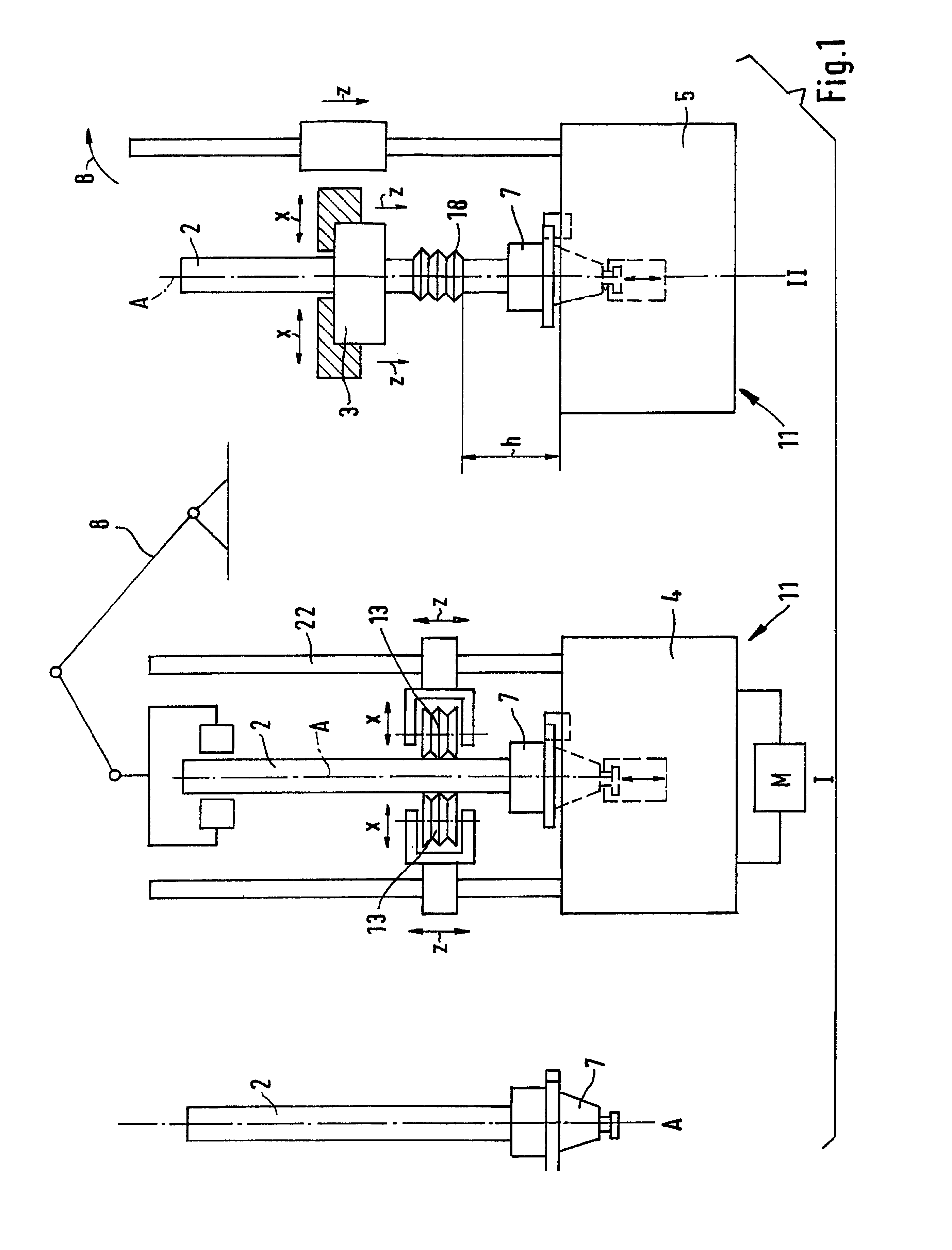
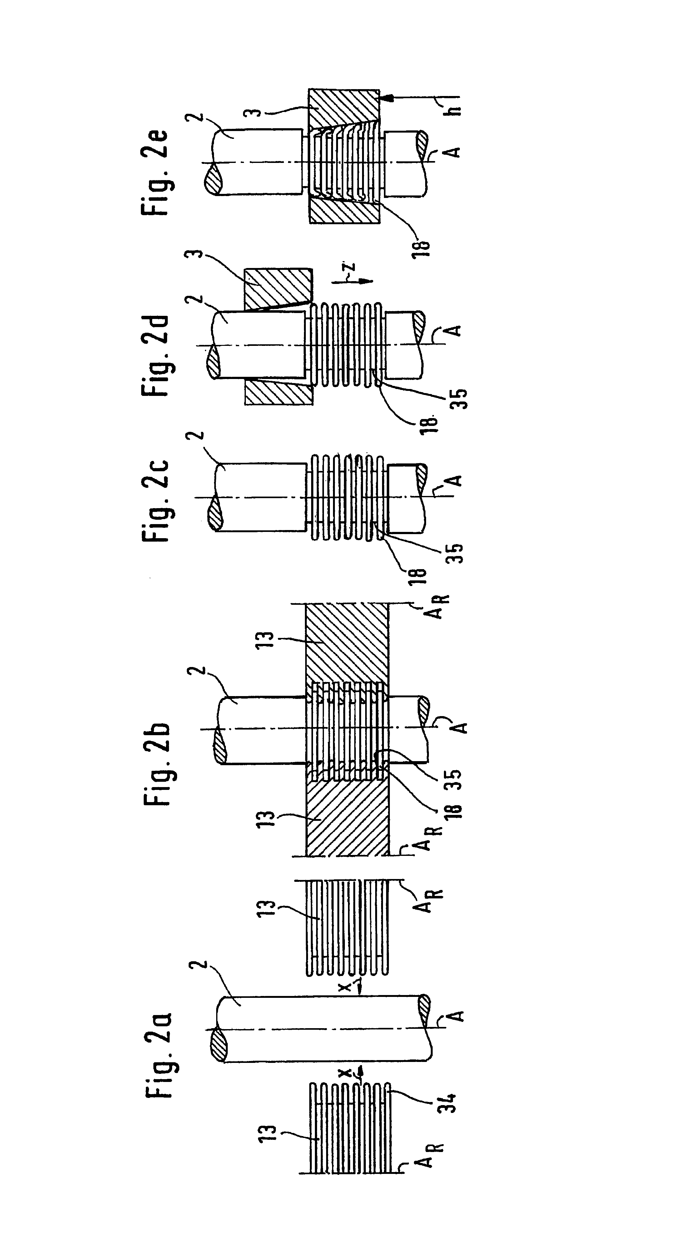
[0056]As shown in FIG. 1, a machining line for producing a camshaft 1 comprising a shaft 2 and a number of cams 3 pressed thereon substantially comprises two machining stations 11. The shaft 2 with a positioning element 7 affixed thereon is transported by means of a manipulating device 8 to the first machining station 11, a knurling station 4. The shaft 2 is fixedly clamped in the knurling station by means of the positioning element 7 and is fixed there so that it can rotate about an axis A. A motor M, preferably a controlled electric motor, ensures that the shaft 2 rotates. The knurling station 4 comprises rollers 13 which can be displaced in the x-direction and in the z-direction. During the rolling process the shaft 2 and the positioning element 7 ...


PUM

PropertyMeasurementUnit
areaaaaaaaaaaa
heightaaaaaaaaaa
circumferenceaaaaaaaaaa

Abstract

An arrangement and method for producing a camshaft comprised of a shaft (2) and of a number of cams (3, 3′, 3″) pressed thereon comprises at least two machining stations (11) of which at least one is provided in the form of knurling station (4) and at least one is provided in the form of a press-on station (5). A shaft (2) is firstly fixed in a brandishing station (4) with the aid of a positioning element (7) fastened to the shaft, and the shaft is subsequently brandished. Afterwards, a cam (3) is pressed onto the shaft (2) in a press-on station (5). To this end, the press-on station (5) comprises a workpiece holder, which corresponds to the positioning element and which serves to provide a holding, particularly to provide an angle-precise holding, of the shaft (2) with the positioning element (7) fastened thereto.

Description

CROSS-REFERENCE TO RELATED APPLICATIONS[0001]This application is an U.S. national phase application under 35 U.S.C. §371 based upon International Application No. PCT / EP2004 / 013816 filed Dec. 4, 2004. Additionally, this U.S. national phase application claims the benefit of priority of co-pending International Application No. PCT / EP2004 / 013816 filed Dec. 4, 2004, and European Application No. EP 04000410.3 filed Jan. 12, 2004. The entire disclosures of the prior applications are incorporated herein by reference. The international application was published on Jul. 21, 2005 under Publication No. WO 2005 / 066522 A1.STATEMENT REGARDING FEDERALLY SPONSEORED RESEARCH OR DEVELOPMENT[0002]Not ApplicableTHE NAMES OF THE PARTIES TO A JOINT RESEARCH AGREEMENT[0003]Not ApplicableINCORPORAITO-BY-REFERENCE OF MATERIAL SUBMITTED ON A COMPACT DISC[0004]Not ApplicableBACKGROUND OF THE IVENTION[0005]1. Field of the Invention[0006]The invention relates to an arrangement and a method for producing a camsha...

Claims


Application Information

Patent Timeline
Patent Type & Authority Patents(United States)
IPC IPC(8): B21K1/12B65G43/00F16D1/072B21D53/84B23P9/02B23P11/00B23P15/00F01L1/047F16H53/02
CPCB23P9/02B23P11/00B23P15/00F16H53/025B23P2700/02F01L1/047Y10T403/4966F01L2013/0052Y10T29/49945Y10T29/49293F01L2103/00F16D1/072F16D1/092F01L2303/00
Inventor BURGLER, ROBERT
Owner CAMTEC INT AG
Why Eureka
Try Eureka