Systems and methods for detecting particles

a particle detection and nano-level technology, applied in the field of systems and methods for detecting particles, can solve the problems of easy loss of collection efficiency of graded metal meshes, inability to detect particles in time, so as to reduce desorption time and high thermal conductivity

Active Publication Date: 2010-05-25
RAPISCAN SYST INC (US)
View PDF22 Cites 18 Cited by
  • Summary
  • Abstract
  • Description
  • Claims
  • Application Information

AI Technical Summary

Benefits of technology

[0009]The embodiments described herein provide high sensitivity and high throughput. More specifically, the embodiments described herein provide a detector including a plurality of jets and a preconcentrator having a screen and a filter. The jets blow air on an individual to dislodge particles from the individual's clothes and skin, thus increasing a concentration of particles entrained in the individual's convention plume. The time required to evaporate particles from an individual's convection plume is decreased by increasing the effective area of the preconcentrator and surrounding the screen with a frame having high thermal conductivity. Thus, the embodiments described herein use a detector with high sensitivity and high throughput to quickly, accurately and efficiently identify illegal and insidious substances carried by passengers.
[0013]In yet another aspect, an apparatus for detecting particles during inspection is provided. The apparatus includes a preconcentrator configured to decrease desorption time, wherein the preconcentrator comprises a filter encased by a thermally conductive frame.

Problems solved by technology

Terrorism risks continue to exist at transportation facilities, government buildings and other high profile locations where there is a significant flow of pedestrian or vehicular traffic.
However, the graded metal mesh easily loses collection efficiency because it gets dirty and clogs easily.
Narcotics are illegal and insidious.
Efforts to use such devices to check all carry-on bags for trace amounts of explosives or narcotics would impose greater time and cost penalties on the airline industry.
These related approaches provide low sensitivity and low throughput.

Method used


Image

  • Systems and methods for detecting particles
  • Systems and methods for detecting particles
  • Systems and methods for detecting particles

Examples


Embodiment Construction

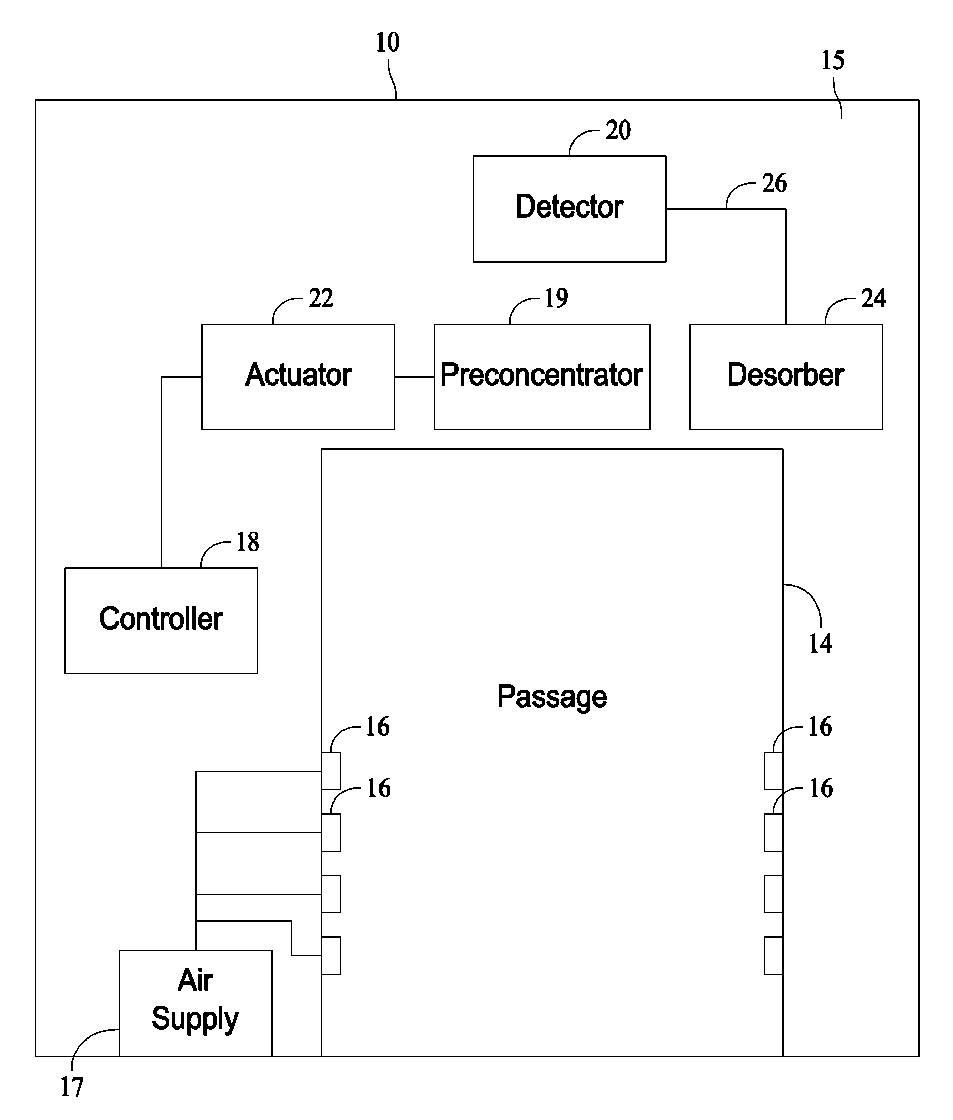
[0022]FIG. 1 is a schematic diagram of an embodiment of a detection system 10. The detection system 10 includes a passage 14 extending through detection system 10. The detection system 10 is installed at a security checkpoint and the passage 14 is dimensioned to conveniently accommodate a person who desires clearance at the security checkpoint. Detector 20 system 10 also includes a chamber 15.

[0023]A boundary layer of air adjacent to the person is heated by the person and generally is hotter than ambient air at farther distances from the person. Hot air is less dense than cooler air and rises relative to the more dense cooler air. As a result, a significant human convection plume of hot air rises in the boundary area adjacent to the person. The human convection plume generally achieves flow rates of 50-100 liters / second. This significant flow of the human convection plume tends to entrain a plurality of particles, such as particles of an explosive material or a narcotic substance, t...


PUM

PropertyMeasurementUnit
thicknessaaaaaaaaaa
flow ratesaaaaaaaaaa
timeaaaaaaaaaa

Abstract

A method of detecting particles during inspection is provided. The method includes establishing a security checkpoint including a detection system, wherein the detection system includes a chamber defining a passage and includes a plurality of jets. The method also includes passing an individual through the passage, enhancing a convection plume including particles from the individual by blowing air through at least one of the plurality of jets, and absorbing the particles in a preconcentrator including a filter encased in a frame having a high thermal conductivity. Moreover, the method includes evaporating the particles absorbed in the preconcentrator and using a detector to determine whether the particles are from at least one of an explosive material and a narcotic substance.

Description

CROSS REFERENCE TO RELATED APPLICATION[0001]The present application relates to and claims priority from Provisional Application Ser. No. 60 / 784,413, filed Mar. 21, 2006, titled “SYSTEMS AND METHODS FOR DETECTING PARTICLES”, the complete subject matter of which is hereby expressly incorporated by reference in its entirety.BACKGROUND OF THE INVENTION[0002]Embodiments of this invention relate generally to systems and methods for detecting particles, and more particularly, to systems and methods for detecting nanogram levels of particles.[0003]Terrorism risks continue to exist at transportation facilities, government buildings and other high profile locations where there is a significant flow of pedestrian or vehicular traffic. As a result, most airports and many government buildings now include apparatus for detecting trace amounts of explosives. These devices typically operate on the principle that small amounts of the explosive materials will be transferred to the body, clothing and ...

Claims


Application Information

Patent Timeline
Patent Type & Authority Patents(United States)
IPC IPC(8): G01N37/00
CPCB01D46/0001B01D46/0016G01N1/2205B01D46/10G01N2001/024
Inventor PERRY, KEVIN JOSEPHKNAPP, MATTHEW EDWARD
Owner RAPISCAN SYST INC (US)
Why Eureka
Try Eureka