Circulation fluidized bed swirl-direct flow composite fluidizing device
A circulating fluidized bed and chemical device technology, applied in chemical instruments and methods, chemical/physical processes, separation methods, etc., can solve the problems of high internal circulation rate, affecting the uniformity of the desulfurization tower, air flow deflection, etc.
- Summary
- Abstract
- Description
- Claims
- Application Information
AI Technical Summary
Problems solved by technology
Method used
Image
Examples
Embodiment 1
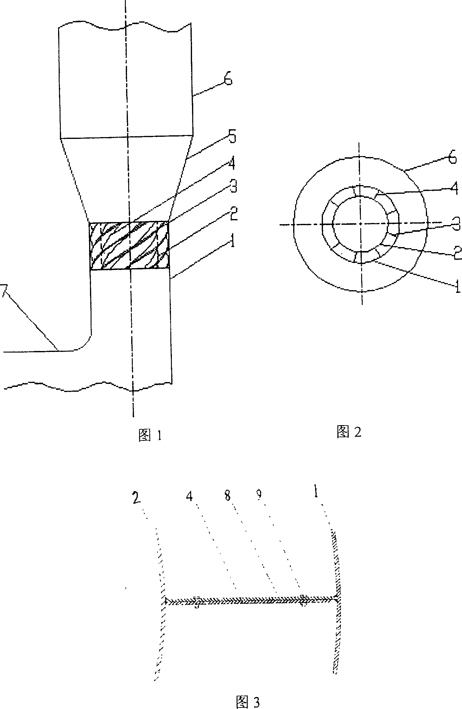
[0016] Example 1: For medium- or low-temperature circulating fluidized bed semi-dry flue gas desulfurization, the flue gas flows in horizontally through the inlet flue 7, rotates 90 degrees and then flows vertically upward through the venturi tube throat 1 and gradual expansion Section 5, enters the desulfurization tower. The inner sleeve 2 is installed in the Venturi tube throat 1, which is coaxial with the Venturi tube throat 1, and has a circular cross-section, whose cross-sectional area accounts for 60% of the Venturi tube throat 1, and the wall surface and the Venturi tube throat The walls of 1 are parallel, and the flue gas flowing in it is DC fluidization; between the inner sleeve 2 and the Venturi throat 1 is the swirl fluidization device 3, and the cross-sectional area of the swirl fluidization device 3 occupies the venturi throat 40% of the cross-sectional area of the pipe 1, the swirl fluidization device 3 is composed of 9 rotating blades 4, and the swirl fluidi...
Embodiment 2
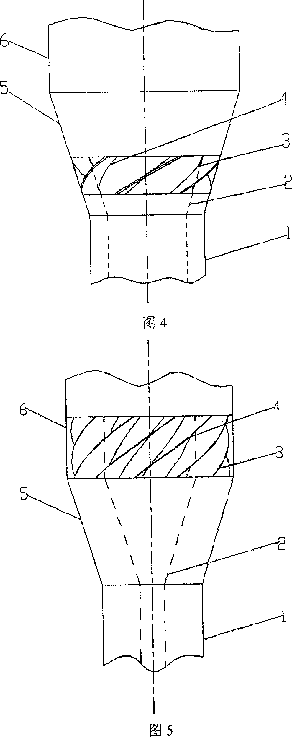
[0017] Embodiment 2: The lower end of the inner sleeve 2 is located in the Venturi tube throat 1, and the upper end is located at half the height of the Venturi tube expansion section 5, and the cross-sectional area accounts for 70% of the cross-sectional area of the Venturi tube expansion section 5 at the same height. , the wall surface of the inner sleeve 2 is parallel to the wall surface of the Venturi expanding section 5 and the Venturi tube throat 1 . The swirl fluidization device 3 is located between the expanding section 5 of the Venturi tube and the inner sleeve, the upper end of the swirling fluidization device 3 is flush with the upper end of the inner sleeve 2, and the cross-sectional area of the upper end occupies the same height as the venturi tube expansion 30% of the cross-sectional area of the section 5, the height of the swirling fluidization device 3 is 30% of the height of the expanding section 5 of the Venturi tube, and there are 6 rotating blades 4 wi...
Embodiment 3
[0018] Embodiment 3: The lower end of the inner sleeve 2 is located in the Venturi throat 1, and the upper end is located at the lower part of the desulfurization tower cylinder 6, and the cross-sectional area of the inner sleeve 2 in the desulfurization tower cylinder 6 accounts for 10% of the desulfurization tower cylinder 6. 30% of the cross-sectional area, the wall surface of the inner sleeve 2 is parallel to the wall surfaces of the desulfurization tower body 6, the Venturi tube gradual expansion section 5, and the Venturi tube throat 1 respectively. The swirl fluidization device 3 is located between the desulfurization tower body 6 and the inner sleeve 2 , the upper end is flush with the upper end of the inner sleeve 2 , and the lower end is located at the inlet of the desulfurization tower body 6 . The cross-sectional area of the swirl fluidization device 3 accounts for 70% of the cross-sectional area of the desulfurization tower cylinder 6, and there are 15 rotati...
PUM
 Abstract
Description
Claims
Application Information
 - R&D
- Intellectual Property
- Life Sciences
- Materials
- Tech Scout
- Unparalleled Data Quality
- Higher Quality Content
- 60% Fewer Hallucinations
Browse by: Latest US Patents, China's latest patents, Technical Efficacy Thesaurus, Application Domain, Technology Topic, Popular Technical Reports.
© 2025 PatSnap. All rights reserved.Legal|Privacy policy|Modern Slavery Act Transparency Statement|Sitemap|About US| Contact US: help@patsnap.com


