ArH cleaning method for carbon pollution on surface of optical element

A technology for optical components and carbon pollution, applied in optical components, optics, instruments, etc., can solve the problems of low efficiency of hydrogen atom clearing, achieve the effects of avoiding adverse effects, improving cleaning efficiency, and maintaining particle activity

Inactive Publication Date: 2015-08-26
CHANGCHUN INST OF OPTICS FINE MECHANICS & PHYSICS CHINESE ACAD OF SCI
View PDF7 Cites 3 Cited by
  • Summary
  • Abstract
  • Description
  • Claims
  • Application Information

AI Technical Summary

Problems solved by technology

[0004] In order to solve the problem of low efficiency of hydrogen atom clearing in the prior art, the present invention proposes an efficient and reliable method for cleaning carbon pollution on the surface of EUV multilayer optical components

Method used


Image

  • ArH cleaning method for carbon pollution on surface of optical element

Examples


Embodiment Construction

[0015] The present invention will be described in further detail below in conjunction with the accompanying drawings.

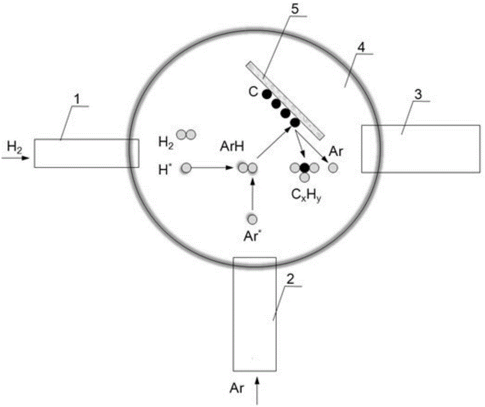
[0016] Such as figure 1 As shown, the cleaning method of the present invention is specifically described by taking the cleaning of carbon contamination on the surface of the Mo / Si multilayer film of the EUV optical element as an example.

[0017] The specific implementation process of the ArH cleaning method for carbon contamination on the surface of optical components is as follows:

[0018] In the first step, the optical element sample 5 contaminated by carbon exposure is placed in the cleaning chamber 4, and the vacuum pump 3 is used to make the cleaning chamber 4 reach a vacuum degree of 10 -5 above mbar.

[0019] The second step is to start the radio frequency plasma emitter 2, the radio frequency is 13.56MHz, and the argon gas is fed in, and the supply flow rate is 2 sccm, so that the whole cleaning chamber 4 is filled with excited argon particles, an...


PUM


Abstract

An ArH cleaning method for carbon pollution on surface of an optical element belongs to the technical field of optical processing. The ArH cleaning method comprises the steps of placing an optical element sample in a cleaning chamber, satisfying a requirement that the vacuum degree of the cleaning chamber is above 10-5mbar by means of a vacuum pump; starting an RF plasma transmitter with an RF frequency of 13.56MHz, introducing argon with a supplying flow of 2sccm, so that the whole cleaning chamber is filled with excited-state argon particles, thereby preventing direct emission to the surface of the optical element sample when the argon is introduced, and preventing optical element surface damage caused by plasma bombardment on the sample surface; starting a hydrogen atom emitter, setting the heating temperature to 2300K, introducing the hydrogen for a supplying flow of 1sccm, making the generated hydrogen atoms combine with argon particles for obtaining an excited-state complex ArH; leading chemical reaction between the carbon on the optical element sample and the ArH, thereby generating a volatile hydrocarbon; and pumping the hydrocarbon and the argon which returns to a ground state, thereby finishing cleaning.

Description

technical field [0001] The invention relates to an ArH cleaning method for carbon pollution on the surface of an optical element, belonging to the technical field of optical processing. Background technique [0002] In extreme ultraviolet (EUV) lithography technology, under the irradiation of EUV light, the hydrocarbons in the system will be cracked to produce free carbon, which will be adsorbed and deposited on the surface of the optical element, forming carbon pollution, because carbon can absorb EUV band radiation, the reflectivity is greatly affected, which will greatly affect the working efficiency of the optical system. [0003] In order to prolong the service life of EUV multilayer optical components, the carbon deposition pollution on the surface of optical components should be cleaned in time to restore the reflectivity of optical components. The Sandial National Laboratory of the United States proposed to use hydrogen atoms to clean the carbon pollution on the sur...

Claims


Application Information

Patent Timeline
Patent Type & Authority Applications(China)
IPC IPC(8): G02B27/00
CPCG02B27/0006
Inventor 王依卢启鹏彭忠琦龚学鹏
Owner CHANGCHUN INST OF OPTICS FINE MECHANICS & PHYSICS CHINESE ACAD OF SCI
Why Eureka
Try Eureka