Target object detection apparatus for acquiring information concerning target objects based on correlation matrix derived from signal values corresponding to reflected electromagnetic waves

a target object and detector technology, applied in the direction of multi-channel direction-finding systems using radio waves, instruments, measurement devices, etc., can solve the problems of insufficient suppression of the correlation between the received incident waves and the number of antenna elements, and achieve the effect of improving accuracy

Active Publication Date: 2010-05-25
DENSO CORP
View PDF17 Cites 29 Cited by
  • Summary
  • Abstract
  • Description
  • Claims
  • Application Information

AI Technical Summary

Benefits of technology

[0015]It is an objective of the present invention to overcome the above problems, by providing a target object detection apparatus having an array antenna for receiving incident waves, whereby enhanced accuracy is achieved in detecting each of a plurality of target objects even if these objects are stationary with respect to the target object detection apparatus, without requiring an increase in the number of antenna elements constituting the array antenna by comparison with a prior art type of apparatus.
[0018]As a result, the effects of correlation between respective incident radar waves that are reflected from different target objects are effectively suppressed, in the average correlation matrix. The average correlation matrix can thus be applied to derive target object information to a high degree of resolution and accuracy, even when a target object is motionless with respect to the target object detection apparatus.
[0020]High resolution of detecting respective relative directions of a plurality of target objects can thereby be achieved, even if the target objects are stationary with respect to the target object detection apparatus, and without requiring an increased number of antenna elements in the array antenna.
[0022]A high accuracy of detecting the relative velocities of one or more target objects can thereby be achieved.

Problems solved by technology

Hence such a method has the disadvantage that, by comparison with a conventional radar apparatus that is capable of detecting the same number of directions of incident waves, the number of antenna elements (and hence the overall size of the radar apparatus) becomes substantially greater.
However a basic problem of such a known type of time-domain averaging method is as follows.
When it is required to detect the incoming directions of reflected waves from one or more target objects which are each stationary with respect to the radar apparatus, it is not possible to achieve a sufficient degree of suppression of the correlation between the received incident waves.

Method used


Image

  • Target object detection apparatus for acquiring information concerning target objects based on correlation matrix derived from signal values corresponding to reflected electromagnetic waves
  • Target object detection apparatus for acquiring information concerning target objects based on correlation matrix derived from signal values corresponding to reflected electromagnetic waves
  • Target object detection apparatus for acquiring information concerning target objects based on correlation matrix derived from signal values corresponding to reflected electromagnetic waves

Examples


first embodiment

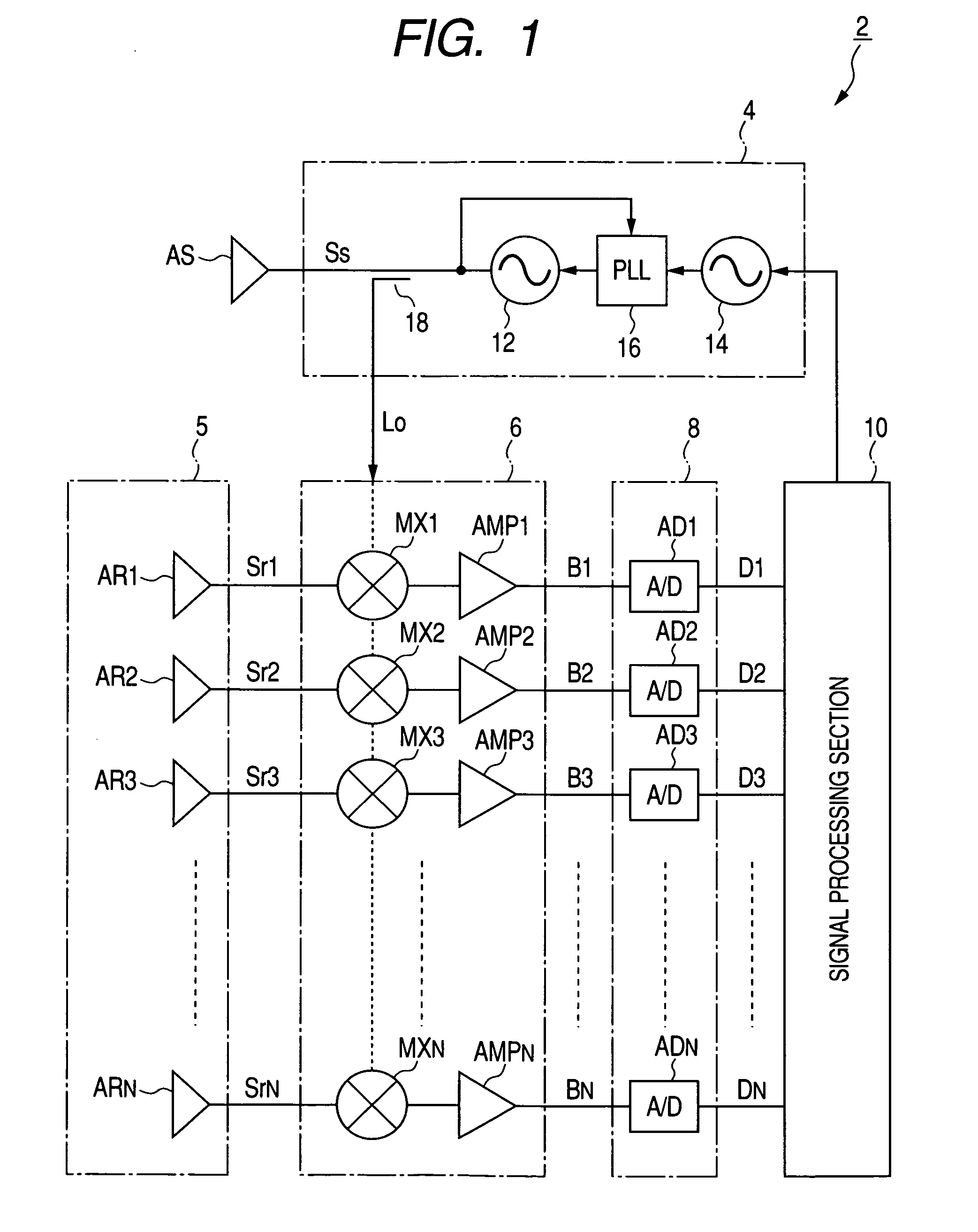
[0036]FIG. 1 is a block diagram showing the overall configuration of an embodiment of a vehicle-installation radar apparatus, designated by numeral 2. As shown, the radar apparatus 2 includes a transmitter 4, a receiving array antenna 5, a receiver 6, a A / D converter section 8 and a signal processing section 10, together with a single-element transmitting antenna designated as AS. The transmitter 4 generates a frequency-modulated high-frequency transmission signal which is supplied to the transmitting antenna AS, for transmitting electromagnetic waves (radar waves) in the millimeter waveband. The receiving array antenna 5 is formed of a set of N antenna elements AR1 to ARN arrayed at equidistant spacings. The receiver 6 is supplied with high-frequency received signals Sr1 to SrN from the N antenna elements AR1 to ARN respectively, resulting from reflected radar waves that are incident on these antenna elements, i.e., waves which have been transmitted from the antenna AS and reflecte...

second embodiment

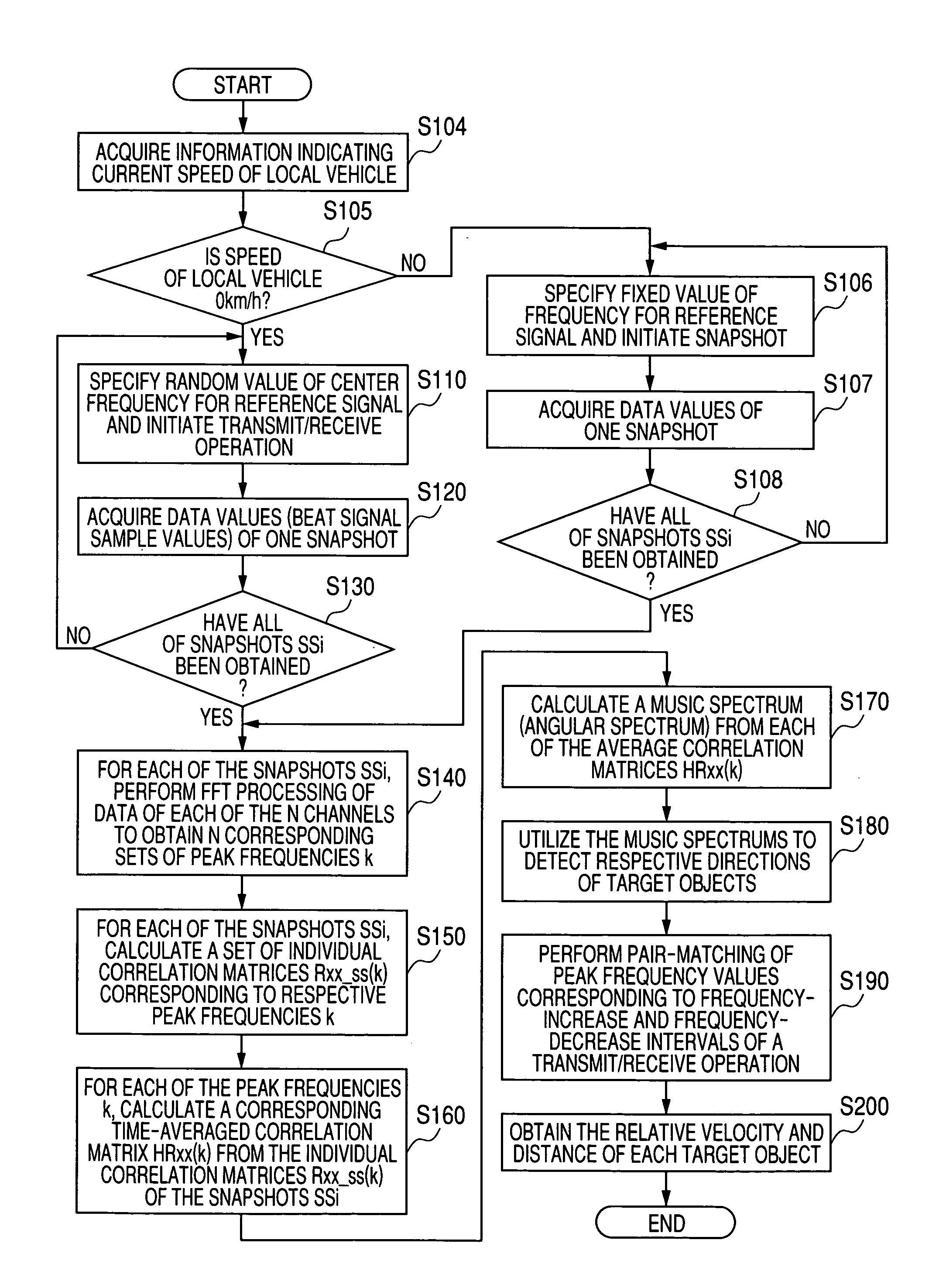
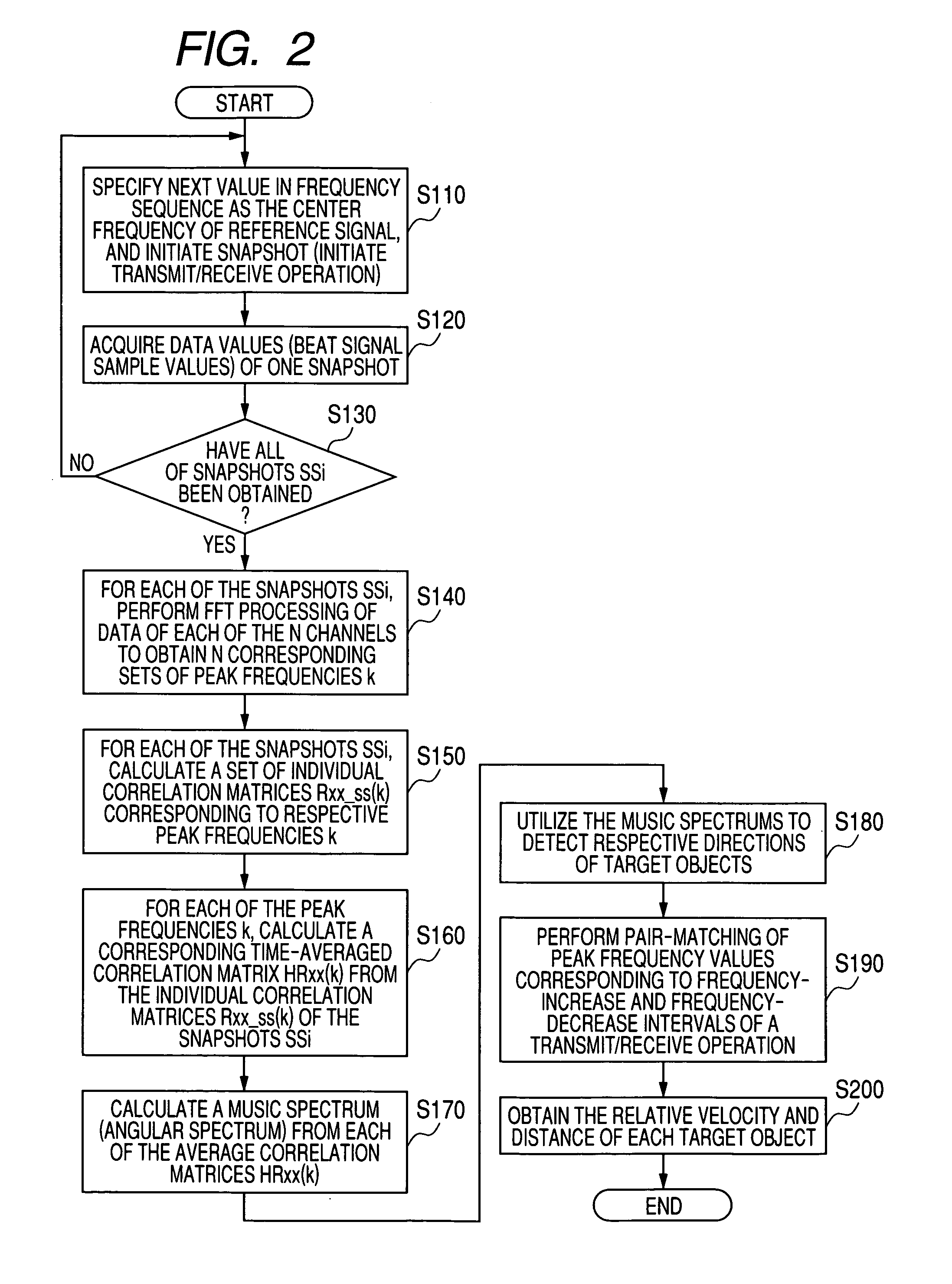
[0079]FIG. 5 shows the overall configuration of a second embodiment, which is a radar apparatus 2a. The radar apparatus 2a differs from the first embodiment only with respect to the receiving system and the contents of processing that is executed by the signal processing section 10, and only these different features will be described in detail in the following. With the second embodiment, a high accuracy of detecting respective relative velocities of one or more target objects can be achieved. This is done by achieving a high resolution of detecting respective component frequencies of a beat signal that is derived from a received signal.

[0080]As shown in FIG. 5 the receiving system of the radar apparatus 2a incorporates a receiving antenna AR1 formed of a single antenna element, in conjunction with a mixer MX1, an amplifier AMP1 and an A / D converter AD1. The reference signal generating circuit 14 of this embodiment is controlled to generate a reference signal which is held at a fixe...


PUM


Abstract

A target object detection apparatus periodically executes a transmit / receive operation to transmit radar waves and obtain received signals from resultant incident reflected waves from respective target objects. An individual correlation matrix of received signal values is derived for each one of a fixed plurality of successive transmit / receive operations, with the transmission frequency being changed at successive operations. Individual correlation matrices derived from respective transmit / receive operations are time-averaged to obtain an average correlation matrix for use in obtaining target object information such as direction or velocity, with effects of correlation between respective incident waves being suppressed.

Description

CROSS-REFERENCE TO RELATED APPLICATIONS[0001]This application is based on and incorporates herein by reference Japanese Patent Application No. 2008-158231 filed on Jun. 17, 2008.BACKGROUND OF THE INVENTION[0002]1. Field of Application[0003]The present invention relates to an apparatus for detecting information relating to target objects that are scanned by electromagnetic waves, with the detection based upon a correlation matrix derived from received signals which correspond to reflected waves from the target objects.[0004]2. Description of Related Art[0005]A target object detection method referred to as the super-resolution method is known, which utilizes an array antenna formed of a plurality of antenna elements for estimating respective incoming directions of a plurality of electromagnetic waves that are incident on the antenna. The method is based on a correlation matrix which expresses correlation between respective received signals of the antenna elements, with the correlation...

Claims


Application Information

Patent Timeline
Patent Type & Authority Patents(United States)
IPC IPC(8): G01S13/42
CPCG01S13/426G01S3/74G01S2013/0263
Inventor NATSUME, KAZUMA
Owner DENSO CORP
Why Eureka
Try Eureka