
Ventilated face shield assembly with glare shield

a face shield and ventilated technology, applied in the field of headmounted face shields, can solve the problems of eye fatigue and facial fatigue, loss of productivity or errors, interfering with vision through the face shield, etc., and achieve the effects of convenient manufacture, enhanced ventilation, and reduced production costs

Active Publication Date: 2010-06-01
OP D OP
View PDF13 Cites 33 Cited by
  • Summary
  • Abstract
  • Description
  • Claims
  • Application Information

AI Technical Summary

Benefits of technology

"The present invention is a ventilated face shield assembly and method of making it that provides enhanced ventilation, glare control, and comfort. The assembly includes a flexible face shield, a flexible glare shield, and a forehead spacer that positions the face shield in separation from the front and sides of the wearer's face. The glare shield can control glare and protect the eyes and face from falling debris. The assembly is designed to be lightweight, easy to manufacture, and assembled at the point of use. The invention also provides a means for retaining the face shield in the arcuate configuration for better ventilation and comfort. The assembly can be stored flat for easy storage and transportation."

Problems solved by technology

Glare causes eye fatigue and facial fatigue from squinting and can contribute to loss of productivity or errors over an extended period of time.
In certain light conditions, parts of eye glasses worn by the user are reflected on the inside of a face shield thereby interfering with vision through the face shield.
Medical face shields are used to prevent transfer of pathogens and, during use, can become contaminated by these pathogens.

Method used


Image

  • Ventilated face shield assembly with glare shield
  • Ventilated face shield assembly with glare shield
  • Ventilated face shield assembly with glare shield

Examples


Embodiment Construction

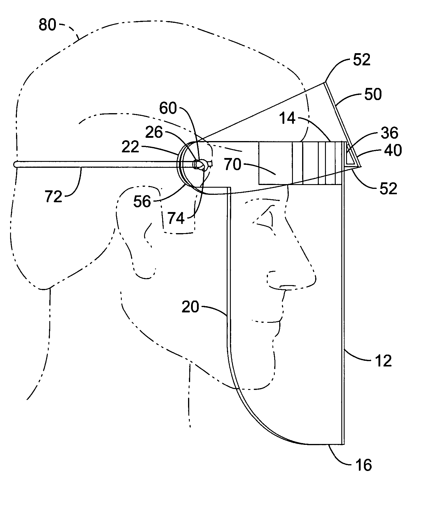
[0083]Referring more specifically to the drawings, for illustrative purposes the present invention is embodied in the apparatus generally shown in FIG. 1 through FIG. 28. It will be appreciated that the apparatus may vary as to configuration and as to details of the parts, and that the method may vary as to the specific steps and sequence, without departing from the basic concepts as disclosed herein.

[0084]In the context of this invention, inside surface refers the surface facing the wearer when a ventilated face shield is worn. Left and right are from a position facing the wearer when a ventilated face shield is worn.

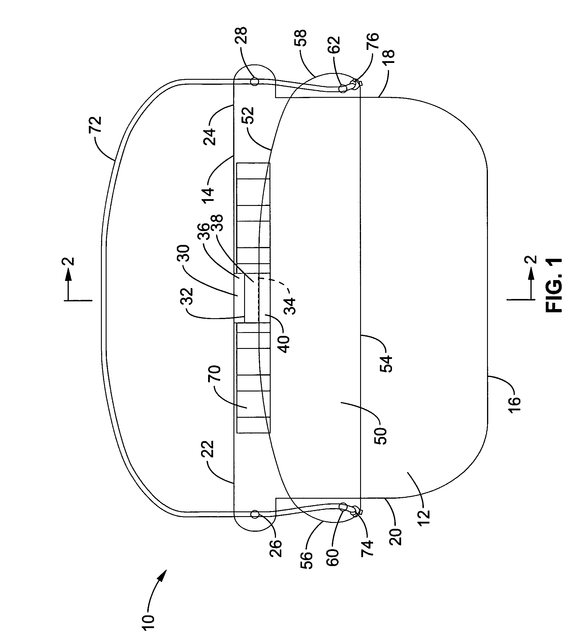
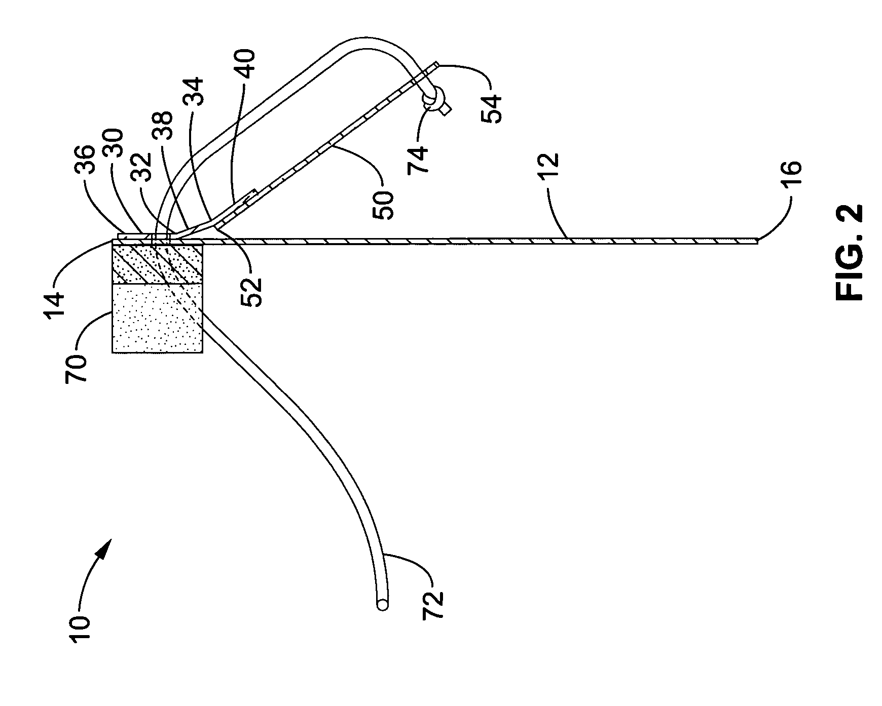
[0085]FIG. 1 through FIG. 3 illustrate an embodiment of a ventilated face shield assembly, according to the present invention. In FIG. 1, a ventilated face shield assembly 10 is assembled and configured prior to use. A face shield of transparent flexible sheet material 12 is configured to cover the front and both sides of the face as well as the forehead and below the ...


PUM


Abstract

A ventilated face shield assembly with a glare shield which protects the face of the wearer from debris and / or hazardous materials, such as biological materials, and is particularly well suited for medical and dental applications. A ventilated headband is used as a spacer and to support the face shield assembly on the face of the wearer. The glare shield and face shield are made of sheet material and are configured for flat storage. In one embodiment, the glare shield and face shield are coupled with a hinge and a flexible cord retains the glare shield and face shield in an arcuate configuration. In another embodiment, a protective breathing mask is attached to the face shield assembly and supports the glare shield and face shield. In a further embodiment, the glare shield is used as the spacer for the face shield.

Description

CROSS-REFERENCE TO RELATED APPLICATIONS[0001]This application claims priority from U.S. provisional application Ser. No. 60 / 560,801 filed on Apr. 7, 2004, incorporated herein by reference in its entirety, and from U.S. provisional application Ser. No. 60 / 578,625 filed on Jun. 9, 2004, incorporated herein by reference in its entirety.STATEMENT REGARDING FEDERALLY SPONSORED RESEARCH OR DEVELOPMENT[0002]Not ApplicableINCORPORATION-BY-REFERENCE OF MATERIAL SUBMITTED ON A COMPACT DISC[0003]Not ApplicableNOTICE OF MATERIAL SUBJECT TO COPYRIGHT PROTECTION[0004]A portion of the material in this patent document is subject to copyright protection under the copyright laws of the United States and of other countries. The owner of the copyright rights has no objection to the facsimile reproduction by anyone of the patent document or the patent disclosure, as it appears in the United States Patent and Trademark Office publicly available file or records, but otherwise reserves all copyright rights...

Claims


Application Information

Patent Timeline
Patent Type & Authority Patents(United States)
IPC IPC(8): A41B13/00A42B1/00A61F9/02A61F9/04A62B18/00
CPCA61F9/022A61F9/045A61F9/029A62B18/003A41D13/1184
Inventor LANDIS, TIMOTHY J.
Owner OP D OP
Learn More