Method and apparatus for converting constant-volume supply fans to variable flow operation

a technology of constant-speed supply fans and variable-flow operation, which is applied in the direction of ventilation systems, heating types, instruments, etc., can solve the problems of inefficient constant-speed hvac systems, inconvenient conversion, and high conversion costs, so as to reduce the speed of the supply fan, improve energy efficiency, and reduce the effect of fan speed

Active Publication Date: 2010-06-01
VIGILENT CORP
View PDF14 Cites 25 Cited by
  • Summary
  • Abstract
  • Description
  • Claims
  • Application Information

AI Technical Summary

Benefits of technology

[0019]In accordance with the present invention, a control system for reducing the speed of the supply fan of a constant-volume HVAC system comprises the supply fan, a fan modulating device, and a plurality of discharge air temperature (DAT) sensors and a controller that calculates the supply fan speed based on the discharge air temperature sensor readings. The controller causes the fan speed to be reduced when the heating or cooling load is less than the design load.OBJECTS OF THE INVENTION
[0020]Accordingly, a primary object of the present invention is to provide a control strategy for fans of constant-volume HVAC systems that can improve the energy efficiency at part-load conditions.
[0021]Another object of the present invention is to provide a control strategy for fans of constant-volume HVAC systems that can improve the energy efficiency at part-load conditions without requiring the installation of mechanical components such as air terminals, dampers or VAV diffusers.
[0023]Another object of the present invention is to provide a control strategy for fans of constant-volume HVAC systems that can improve the energy efficiency at part-load conditions and that uses sensors that are easy to install and that are inexpensive.

Problems solved by technology

Constant-volume HVAC systems are inefficient.
These conversions are very expensive and intrusive because of the mechanical modifications.
This approach is very expensive and very intrusive because it requires significant mechanical modifications.
This approach still requires mechanical modifications.
This strategy does not save energy for systems that are shut off after hours.
Even when there is after-hours operation, this method is not cost effective unless the system is large because the energy savings are limited.
This strategy still requires a mechanical modification, which is intrusive and requires that the system be shut down.
Position sensors are expensive and difficult to install.
Resistive position sensors are prone to vibration-induced premature failure.
This strategy cannot be applied to single-duct constant-volume systems because they do not have mixing dampers.

Method used


Image

  • Method and apparatus for converting constant-volume supply fans to variable flow operation
  • Method and apparatus for converting constant-volume supply fans to variable flow operation
  • Method and apparatus for converting constant-volume supply fans to variable flow operation

Examples


Embodiment Construction

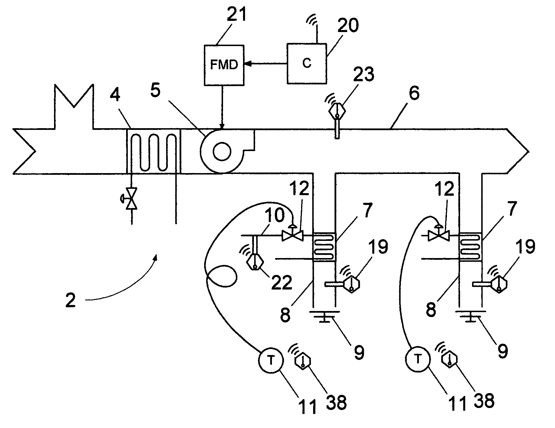
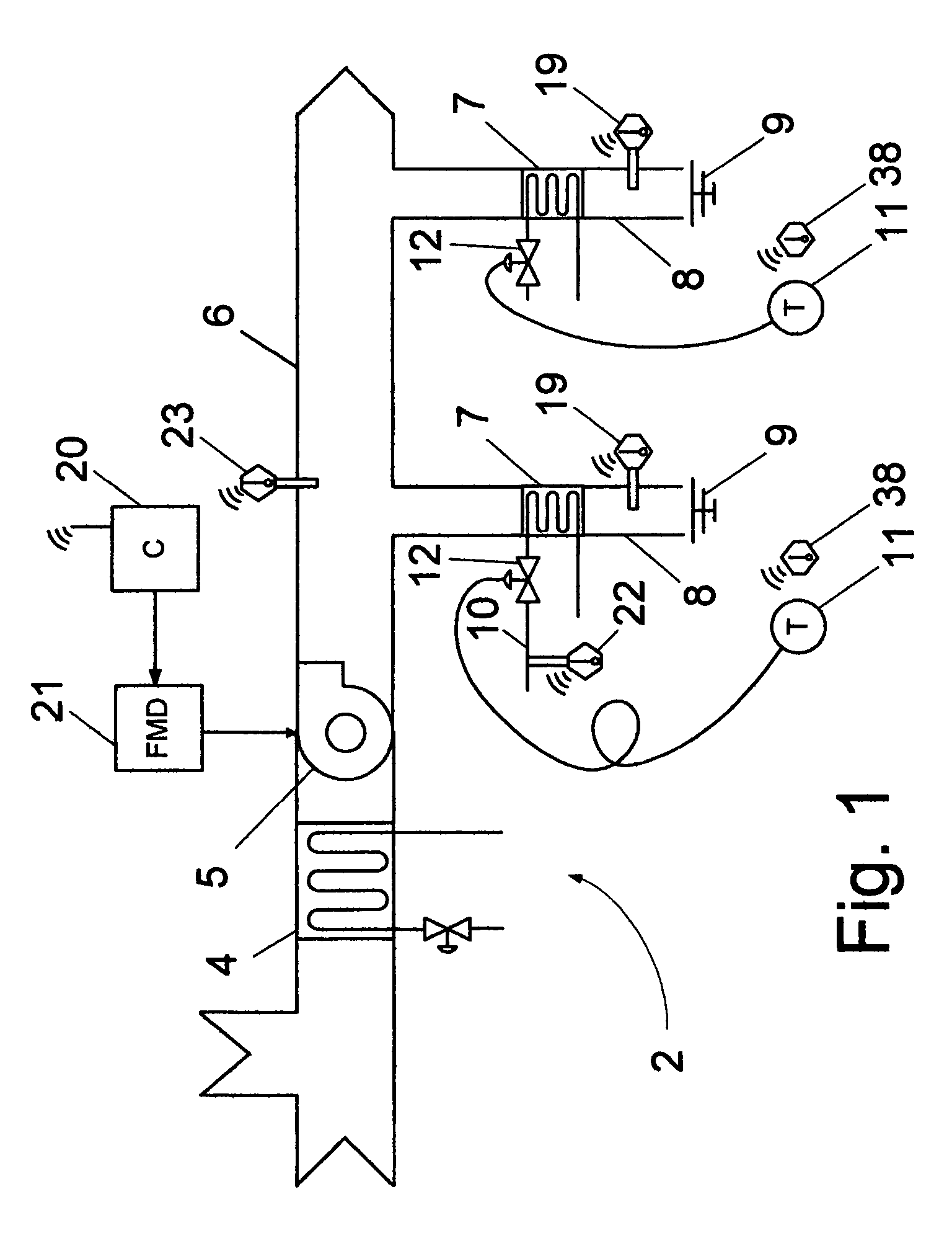
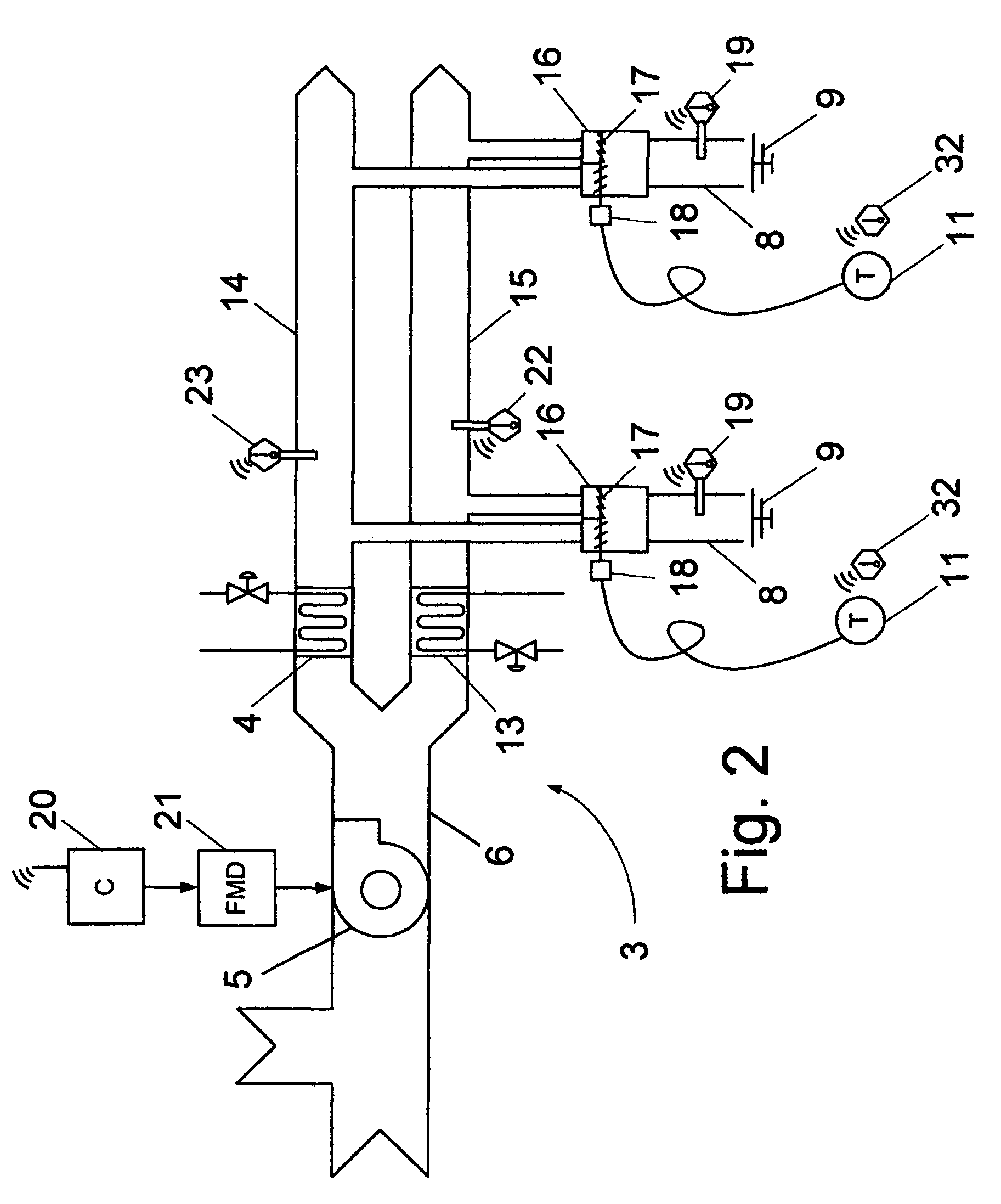
[0033]A preferred embodiment of the supply fan control system is illustrated in FIG. 1-5. HVAC system 1 may be a single-duct re-heat system 2, a dual-duct constant-volume system 3 or a multi-zone system. FIG. 1 shows single-duct system 2. Single-duct systems 2 include a cooling coil 4, a supply fan 5, supply air ducts 6, re-heat coils 7, discharge air ducts 8, and discharge air diffusers 9. Cooling coil 4 is a heat exchanger that carries a cooling fluid such as chilled water or a chilled water and glycol solution. Cooling coil 4 is mounted in supply air duct 6. Supply fan 5 could be a centrifugal fan or an axial fan. Supply fan 5 is mounted in supply duct 6. A duct is an elongate sheet metal structure with round or rectangular cross-section designed to transport air. Supply duct 6 contains branches that lead to re-heat coils 7. Re-heat coil 7 is a heat exchanger that carries heating fluid supplied by a hot water supply pipe 10. It is mounted between a branch of supply duct 6 and dis...


PUM


Abstract

A control strategy for supply fans in constant-volume heating, ventilating, and air-conditioning (HVAC) systems that reduces the speed of the fan at part-load conditions is provided. The invention consists of a constant-volume HVAC system, wireless discharge air temperature sensors, wireless hot source and cold source temperature sensors, and a wireless controller coupled to a fan modulation device. The controller includes a finite state machine that switches between a high-temperature control mode and a low-temperature control mode. The controller also includes a calculator that calculates a high temperature setpoint and a low temperature setpoint as a function of the hot source and cold source temperatures. In high temperature control mode, the controller compares the maximum discharge air temperature with the high temperature setpoint, and it commands the fan modulating device so that the maximum discharge air temperature remains close to the high temperature setpoint. In low temperature control mode, the controller compares the minimum discharge air temperature with the low temperature setpoint, and it commands the fan modulating device so that the minimum discharge air temperature remains close to the low temperature setpoint. Alternatively, the controller includes a calculator that computes a largest load as a function of previous fan command, discharge air temperatures, and readings from wireless zone temperature sensors. The controller increases the speed of the fan as the largest load increases, and reduces the speed of the fan as the largest load decreases.

Description

CROSS-REFERENCE TO RELATED APPLICATIONS[0001]This application claims benefit under Title 35, United States Code §119(e) of U.S. Provisional Application No. 60 / 644,669 filed on Jan. 18, 2005.BACKGROUND[0002]1. Field of the Invention[0003]The following invention relates to controls for fans in heating, ventilating, and air-conditioning (HVAC) systems, specifically to controls for converting constant speed fans to variable flow operation while preserving proper zone temperature control.[0004]2. Description of Prior Art[0005]Modern buildings typically use heating, ventilating, and air-conditioning (HVAC) systems to control indoor temperature, pressure, ventilation rate and other variables. Prior to the oil embargo of the 1970s it was common to design HVAC systems with constant-speed fans and with temperature controls that would re-heat cooled air or mix heated air with cooled air to maintain space temperature. HVAC systems with constant speed fans are called constant-volume systems.[000...

Claims


Application Information

Patent Timeline
Patent Type & Authority Patents(United States)
IPC IPC(8): F24F7/00G01M1/38G05B13/00
CPCF24F11/0012F24F11/0079G05D23/1931Y02B30/746F24F2001/0066F24F11/30F24F2110/10F24F11/77F24F1/00075Y02B30/70F24F11/76F24F11/46F24F11/56F24F2140/00
Inventor FEDERSPIEL, CLIFFORD CONRAD
Owner VIGILENT CORP
Why Eureka
Try Eureka