Stabilized tissue penetrating catheters

a tissue penetrating catheter and stabilizing technology, applied in the field of catheters, can solve the problems of insufficient inclusion of all the elements required for optimal use, inability to precisely target the location, and inability to achieve optimal us

Inactive Publication Date: 2010-06-01
MEDTRONIC VASCULAR INC
View PDF14 Cites 110 Cited by
  • Summary
  • Abstract
  • Description
  • Claims
  • Application Information

AI Technical Summary

Benefits of technology

[0027]Still further in accordance with the invention, the catheter body may incorporate one or more infusion lumens with infusion ports to permit dye or other imageable material to be injected upstream of the deployed stabilizer to check for flow-through or past the stabilizer or alternatively occlusion of the vessel, in situations where it is desired for the stabilizer to effect such occlusion. In this regard, it will be noted that in some applications it may be desirable for the stabilizer to be deployed such that it expands s

Problems solved by technology

Atherosclerotic cardiovascular disease remains a major cause of premature death and morbidity, in most regions of the world.
The prior art has included tissue penetrating catheters for uses other than those claimed in this patent application, but such prior art tissue penetrating catheters fail to include all of the elements required for optimal use in the methods of this invention or for precise targeting of the location at which the penetration tract is to be made.
However, the Faxon et al. de

Method used


Image

  • Stabilized tissue penetrating catheters
  • Stabilized tissue penetrating catheters
  • Stabilized tissue penetrating catheters

Examples


Embodiment Construction

[0056]Set forth herebelow are detailed descriptions of certain embodiments and examples of the catheter devices and methods of the present invention.

[0057]The invention herein utilizes the vascular system as a perfect conduit to any region of the body. The devices, systems and methods described herein provide a new way that the interstitial space can be accessed for surgical, interventional, diagnostic, monitoring or other purposes. The invention provides a system for gaining percutaneous access to any part of the body through the vascular system, and provides the basic set of instrumentation for accomplishing several surgical and medical end-points.

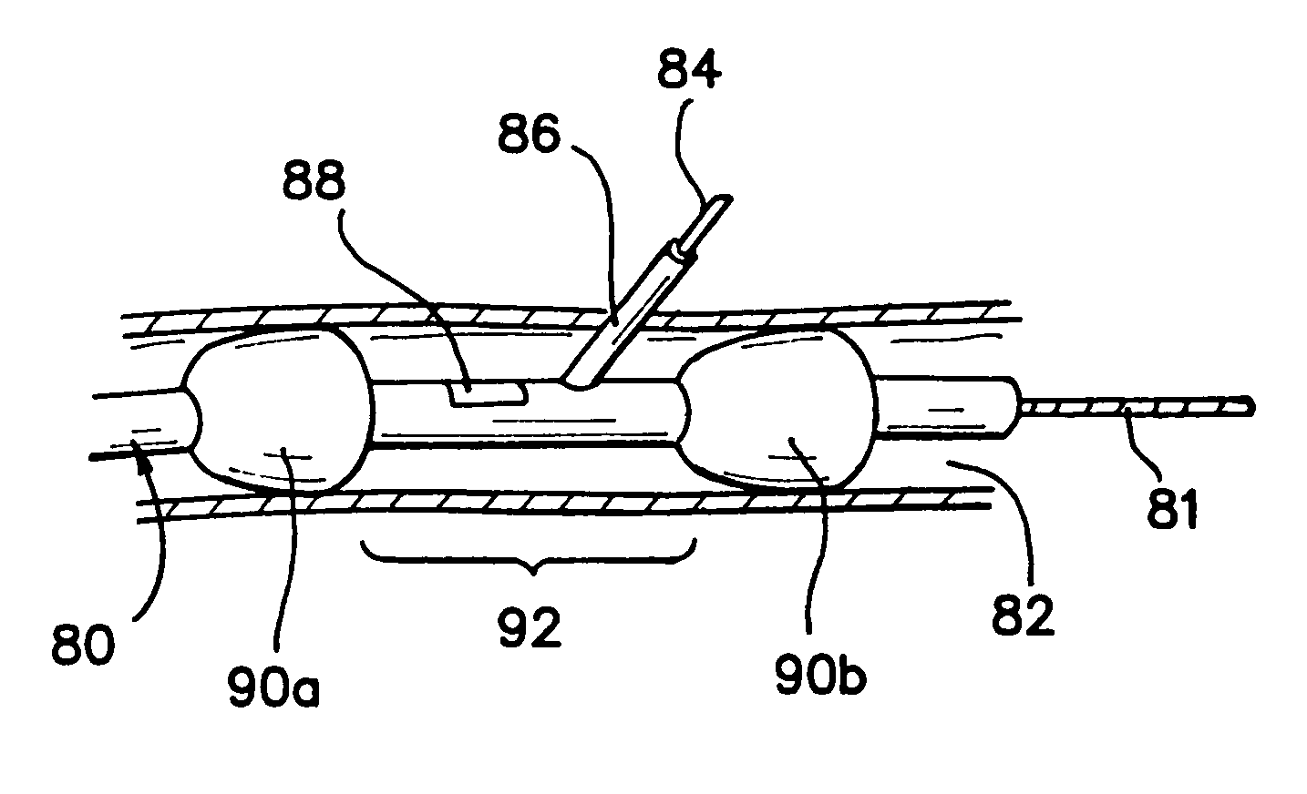
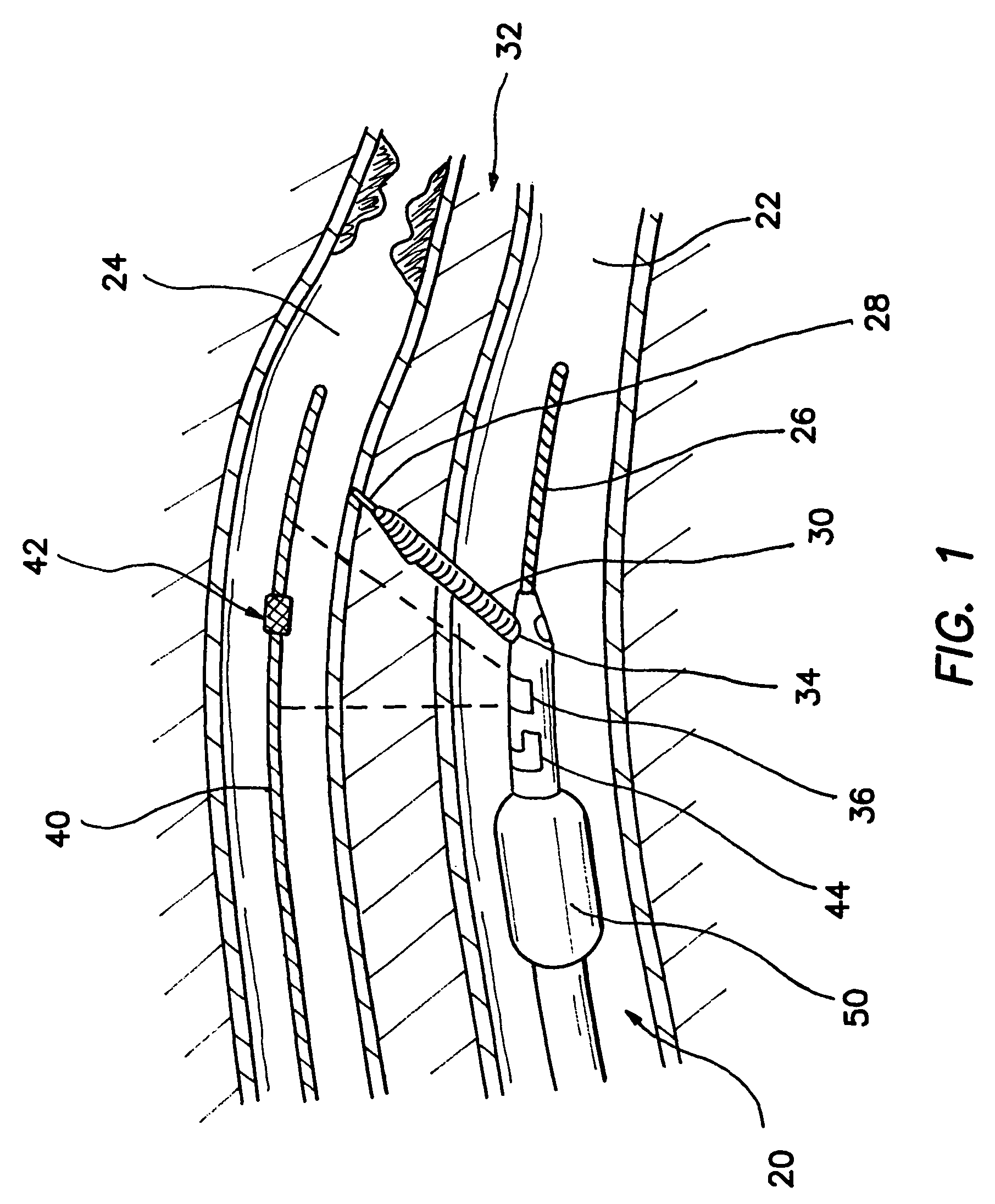
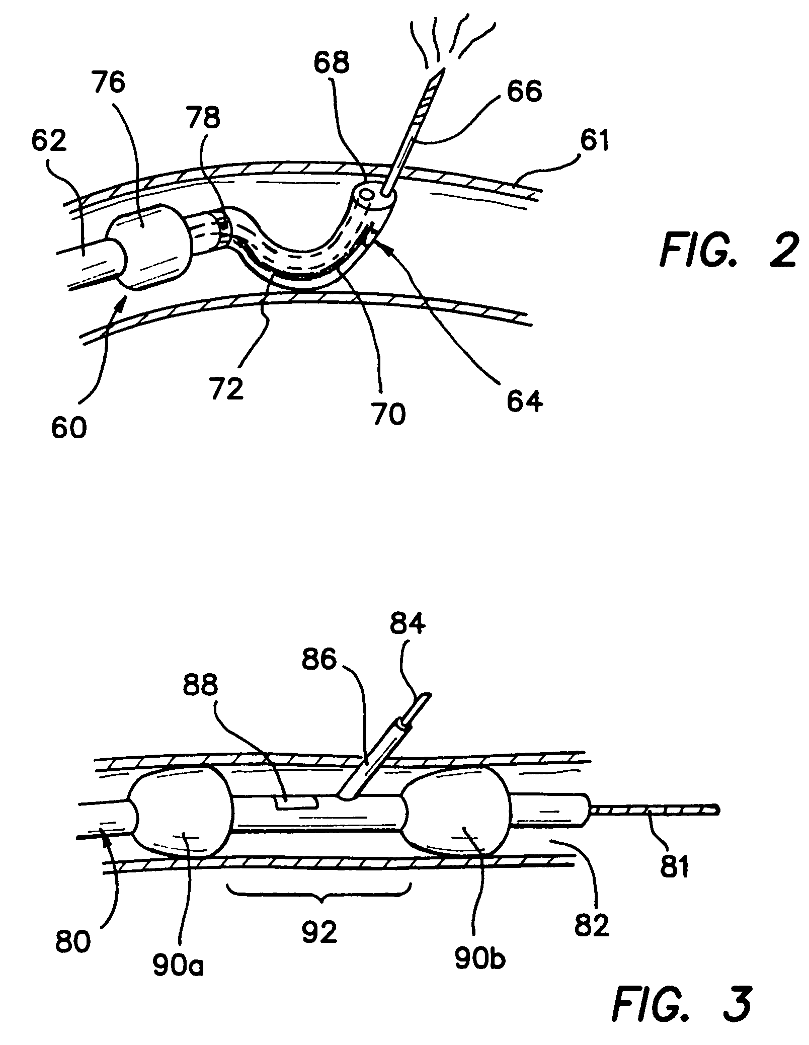
[0058]The stabilized tissue penetrating catheters of the present invention are usable in the performance of certain transluminal catheter-based revascularization procedures such as the PICAB™ and PICVA™ procedures in the heart or peripheral blood vessels as described in Fitzgerald, P. J, New Approaches and Conduits: In Situ Venous Arteri...


PUM

PropertyMeasurementUnit
Flow rateaaaaaaaaaa
Diameteraaaaaaaaaa

Abstract

A tissue penetrating catheter that is usable to advance a tissue penetrator from within a blood vessel, through the wall of the blood vessel to a target location. The catheter includes at least one stabilizing device thereon for stabilizing catheter prior to advancing the tissue penetrator. The tissue penetrator may extend through a lumen in the body of the catheter and project transversely through an exit port. The stabilizing device may be located closely adjacent to the exit port, or may surround the exit port. The stabilizing device may be one or more balloons, or other mechanical structure that is expandable into contact with the inner luminal wall of the blood vessel. Desirably, the exit port is forced into contact with the blood vessel wall to shorten the distance that the tissue penetrator projects from the catheter body to the target location. The catheter is particular useful for forming blood flow tracts between blood vessels, in particular in coronary revascularization procedures. Methods of utilizing such a catheter to bypass an arterial obstruction is also disclosed.

Description

RELATED APPLICATIONS[0001]This application is a continuation-in-part of three-earlier filed and co-pending applications, namely: a) U.S. patent application Ser. No. 09 / 282,774, filed on Mar. 31, 1999, now U.S. Pat. No. 6,375,615 which in turn claims priority to U.S. Provisional Application No. 60 / 080,196, filed Mar. 31, 1998; b) U.S. patent application Ser. No. 08 / 837,294 filed on Apr. 11, 1997 now U.S. Pat. No. 6,302,875, and c) U.S. patent application Ser. No. 09 / 179,809, filed on Oct. 27, 1998, now U.S. Pat. No. 6,068,638 which is a continuation of U.S. patent application Ser. No. 08 / 730,496, filed on Oct. 11, 1996, and now U.S. Pat. No. 5,830,222, and which in turn claims priority to earlier-filed U.S. Provisional Patent Application Nos. 60 / 005,164 filed Oct. 13, 1995 and 60 / 010,613 filed Feb. 2, 1996, the entire disclosures of all such related applications being expressly incorporated herein by reference.FIELD OF THE INVENTION[0002]The present invention relates generally to med...

Claims


Application Information

Patent Timeline
IPC IPC(8): A61B5/05A61B1/313A61B8/12A61B17/00A61B17/064A61B17/11A61B17/12A61B17/22A61B17/30A61B17/34A61B18/00A61B18/14A61B18/24A61B19/00A61F2/00A61F2/02A61F2/90A61K31/195A61M25/00A61M25/01A61M29/00
CPCA61B1/3137A61B8/12A61B17/11A61B17/12022A61B17/12045A61B17/12109A61B17/12136A61B17/12172A61B17/3207A61B17/3417A61B18/1445A61F2/2493A61F2/95A61K31/195A61B8/4488A61B17/00234A61B17/00491A61B17/0057A61B17/0643A61B17/320725A61B17/3496A61B18/00A61B18/1477A61B18/1492A61B18/24A61B19/38A61B19/5212A61B19/54A61B2017/00243A61B2017/00247A61B2017/00252A61B2017/003A61B2017/00455A61B2017/00504A61B2017/00641A61B2017/1107A61B2017/1139A61B2017/12127A61B2017/22038A61B2017/22069A61B2017/22072A61B2017/22077A61B2017/306A61B2017/347A61B2017/3488A61B2018/00392A61B2018/00869A61B2018/1425A61B2019/5276A61B2019/528A61B2019/5425A61B2019/5429A61B2019/5458A61F2/07A61F2/90A61F2002/30079A61F2002/8486A61F2002/9517A61F2210/009A61M25/0147A61M25/0155A61M29/02A61M2025/0076A61M2025/018A61M2025/1052A61B8/445A61B90/361A61B90/39A61B90/40A61B2090/378A61B2090/3784A61B2090/3925A61B2090/3929A61B2090/3958A61F2/9517
Inventor FLAHERTY, J. CHRISTOPHERMAKOWER, JOSHUA
Owner MEDTRONIC VASCULAR INC
Why Eureka
Try Eureka