Electrodes for transcutaneous electrical nerve stimulator

a technology of electric nerve and electrode, which is applied in the direction of external electrodes, electrotherapy, therapy, etc., can solve the problems of many dendrite afferents along longer pathways that do not receive sufficient stimulation, and achieve the effects of improving patient comfort and tolerance of procedure, superior retraining of muscles, and reducing curren

Inactive Publication Date: 2010-06-01
BACOUSTICS LLC
View PDF8 Cites 9 Cited by
  • Summary
  • Abstract
  • Description
  • Claims
  • Application Information

AI Technical Summary

Benefits of technology

[0012]Electrode plates containing a conductive layer containing both an inner perimeter(s) and an outer perimeter(s) have the effect of balancing the impedance between A fiber afferents with dendrites along the shortest paths with A fiber afferents having dendrites along longer pathways, resulting in a balance of electrical current distribution. This serves to both protect short pathway A fiber afferents from over stimulation as well as ensuring long pathway A fiber afferents receive the sufficient amount of stimulation needed to fire. The increased number of A fiber afferents with proper stimulation thus produces a greater rate of A fiber afferent firing within the dorsal horn of the spinal cord. The resulting higher rate of A fiber afferent firing within the dorsal horn of the spinal cord will produce a more stable and persistent LTD in response to C fiber stimulation, increasing the level of analgesia produced to persistent, sustained, lingering pain.
[0015]Another aspect of the invention may be to provide an electrode that reduces the amount of the current required to elicit medical effects such as, but not limited to, the induction of analgesia and the retraining of muscles when the electrode is used with TENS treatment protocols and devices as well as other treatment / therapy methods, thereby improving patient comfort and tolerance of the procedure.
[0016]Another aspect of the invention may be to provide an electrode that reduces the amount of current required to elicit medical effects such as, but not limited to, the induction of analgesia and the retraining of muscles when the electrode issued with TENS treatment protocols and devices as well as other treatment / therapy methods, thereby allowing the construction of smaller and more portable treatment / therapy devices than currently exist.

Problems solved by technology

Therefore, the A fiber afferents with dendrites along the shortest path between the electrodes are stimulated with increased energy / electrical current while many of the A fiber afferents with dendrites along longer pathways do not receive sufficient stimulation.

Method used


Image

  • Electrodes for transcutaneous electrical nerve stimulator
  • Electrodes for transcutaneous electrical nerve stimulator
  • Electrodes for transcutaneous electrical nerve stimulator

Examples


Embodiment Construction

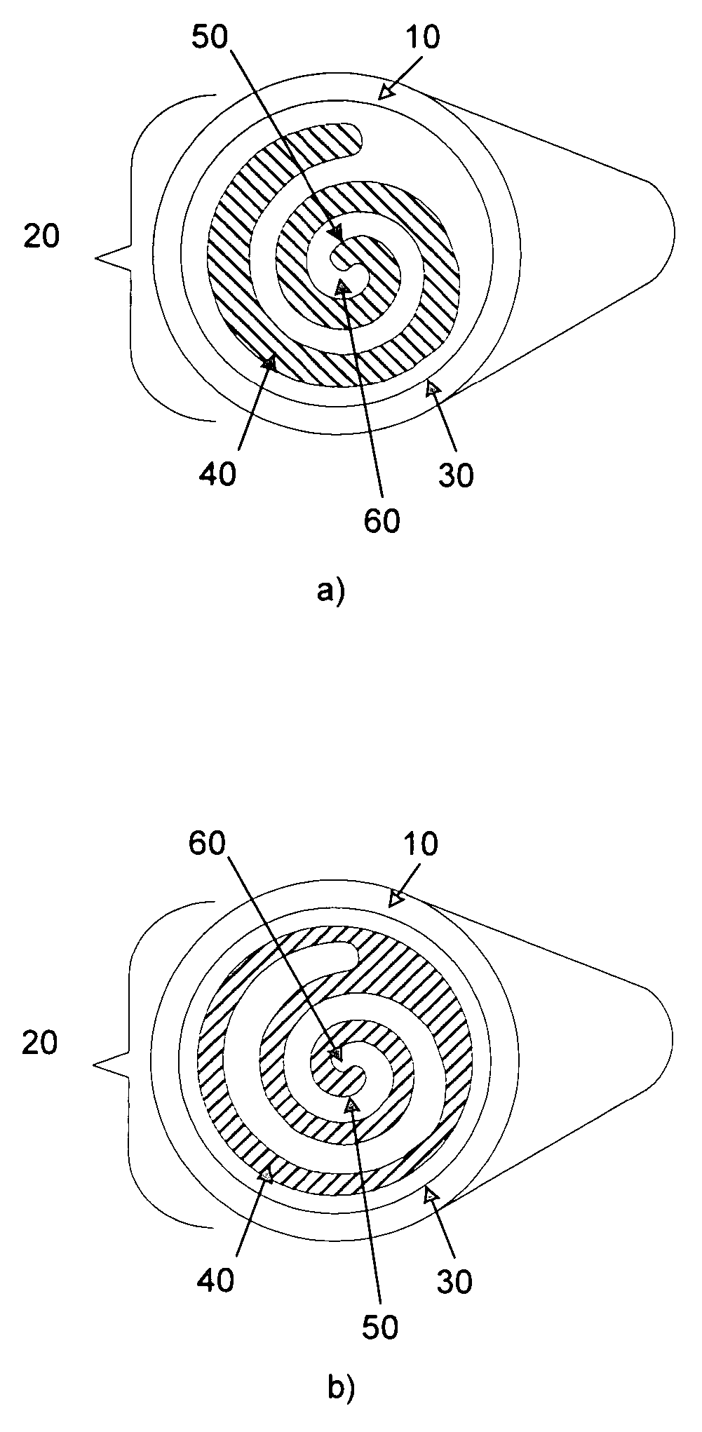
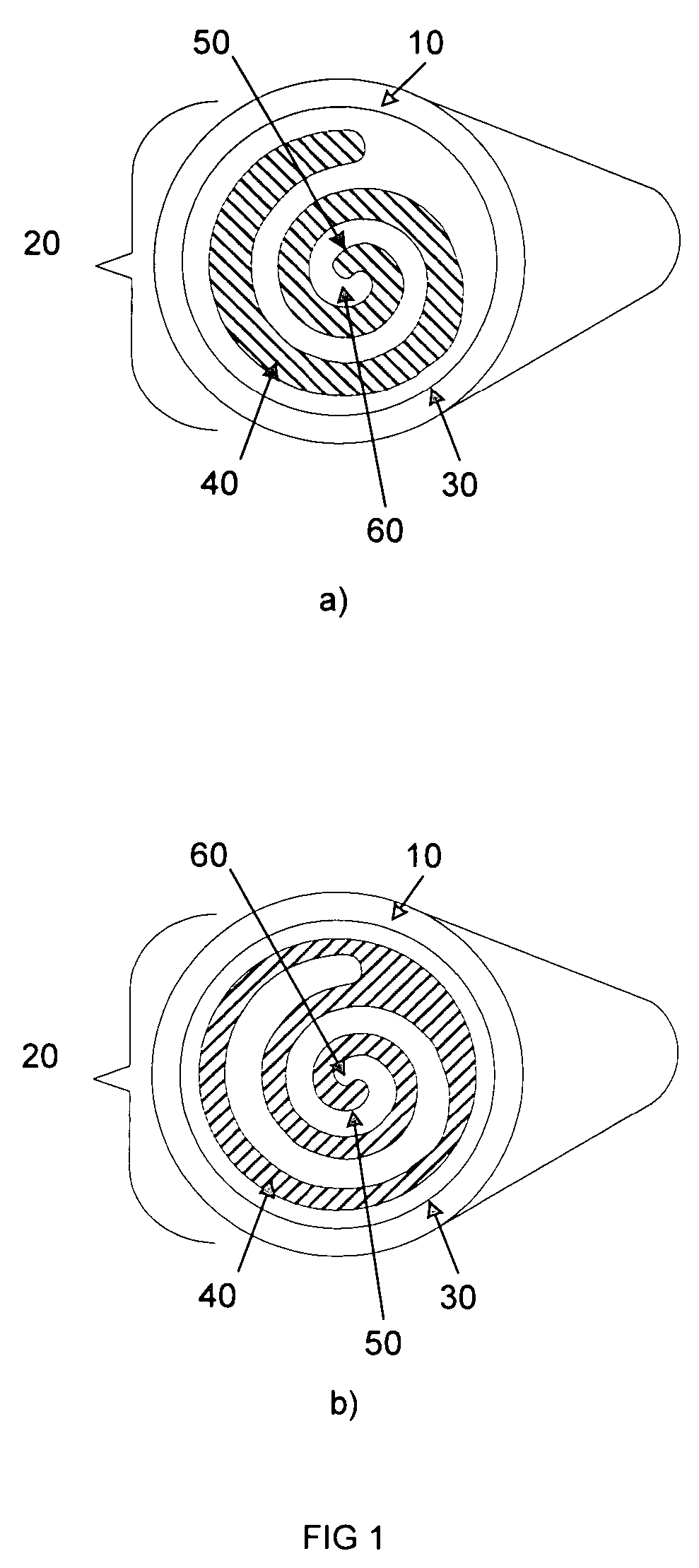
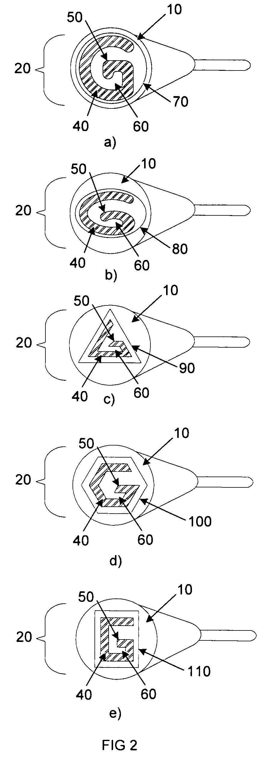
[0023]The basic construction of electrodes for use in Transcutaneous Electric Nerve Stimulation (TENS) is well known in the art and described and disclosed in detail in U.S. Pat. Nos. 4,934,383 (Olumac), 6,907,299 (Han), and 4,926,878 (Snedeker) herein included by reference. Though descriptive of the basic embodiment of a TENS electrode, the use of the present invention is not limited to those specific embodiments. An electrode of the present invention comprises a conductive containing at least one conductive area and at least one non-conductive area, at least one outer perimeter, and at least one inner perimeter.

[0024]FIG. 1(a) depicts the conductive layer (10) of an electrode (20) of one embodiment of the present invention. The outer perimeter (30) is the boundary of the geometric region encompassing the conductive area (40) of the conductive layer (10). The inner perimeter (50) is the boundary of the area (60) within the outer perimeter (30) that contains the non-conductive area....


PUM


Abstract

A transcutaneous electric nerve stimulator (TENS) electrode that comprises a conductive layer containing both an inner perimeter(s) and an outer perimeter(s) is disclosed. When used with TENS treatment protocols and devices or other treatment / therapy methods, the electrode can induce a higher rate of A fiber firing by creating baffling to balance the electrical current flowing through the electrodes and induces superior analgesia.

Description

BACKGROUND OF THE INVENTION[0001]1. Field of the Invention[0002]The present invention relates to a Transcutaneous Electric Nerve Stimulator (TENS) electrode that comprises a conductive layer containing both an inner perimeter(s) and an outer perimeter(s).[0003]2. Description of the Related Art[0004]The conscious perception of pain involves the transmission of sensory information across three primary types of neurons that form a pathway from the body to the brain. Responding directly to the painful stimulus, peripheral afferent fibers transmit a message indicating the presence of pain to intermediate neurons in the dorsal horn of the spinal cord. Acting as middlemen, intermediate neurons in the dorsal horn receive the message of pain from peripheral fibers and relay it to spinal cord neurons projecting to the brain, where the pain is consciously perceived.[0005]Two types of peripheral afferent fibers respond directly to painful stimuli. Fast conducting A fibers respond to the immedia...

Claims


Application Information

Patent Timeline
Patent Type & Authority Patents(United States)
IPC IPC(8): A61N1/04A61N1/18
CPCA61N1/0456A61N1/0492A61N1/36021
Inventor BABAEV, EILAZ
Owner BACOUSTICS LLC
Why Eureka
Try Eureka