Lift truck with hybrid power source

a technology of hybrid power source and lift truck, which is applied in the direction of hybrid vehicles, battery/fuel cell control arrangement, propulsion by capacitors, etc., can solve the problem that refueling requires about one tenth the time needed to replace batteries, and achieve the effect of efficiently storing energy and efficiently recapture energy

Active Publication Date: 2010-06-08
RAYMOND LTD
View PDF13 Cites 75 Cited by
  • Summary
  • Abstract
  • Description
  • Claims
  • Application Information

AI Technical Summary

Benefits of technology

[0007]The present invention is a hybrid power source for an electric lift truck which efficiently recaptures energy regenerated by the traction and lift systems and which generates electrical energy using an on-board fuel cell. The hybrid power source includes a storage battery that may be recharged from external circuitry but in normal truck operation is maintained in a charged condition by an on-board fuel cell. A capacitor bank connects to the storage battery and efficiently stores energy regenerated by the lift system and traction system during truck operation and returns that energy to operate the truck.
[0009]Another general object of the invention is to reduce the amount of truck downtime. Under normal operating conditions the battery does not require replacing, but is instead recharged by the fuel cell. The truck is periodically refueled, but this refueling requires about one tenth the time needed to replace the battery. The fuel cell is sized to provide the total energy needed by the truck over a typical work shift and the storage battery and capacitor bank handle the fluctuations in energy demand that occur over that work shift. The storage battery stores energy produced by the fuel cell during periods of low energy demand and the capacitor bank stores energy during periods of energy regeneration. Both of these storage devices return their stored energy when truck energy demand exceeds the peak capacity of the fuel cell.

Problems solved by technology

The truck is periodically refueled, but this refueling requires about one tenth the time needed to replace the battery.

Method used


Image

  • Lift truck with hybrid power source
  • Lift truck with hybrid power source
  • Lift truck with hybrid power source

Examples


Embodiment Construction

[0018]Referring particularly to FIG. 3, a lift truck which employs a preferred embodiment of the invention includes a power unit 110 having an operator's compartment 112 located to the rear and a power source compartment 114 located at the forward end. As will be described in detail below, a power source including a battery, a capacitor bank, and optionally, a fuel cell are located in the compartment 114, and they supply power to a traction motor drive (not shown) which rotates a steerable drive wheel 116 to propel and steer the lift truck. A pair of laterally spaced baselegs 118 indirectly connect to, and extend forward from the power unit 110, and each baseleg includes wheels 120 which support the truck. A mast 122 connects to the front end of the power unit 110 and extends vertically upward therefrom. The mast 122 supports a fork carriage 124 which can be elevated to different heights by operation of a lift system.

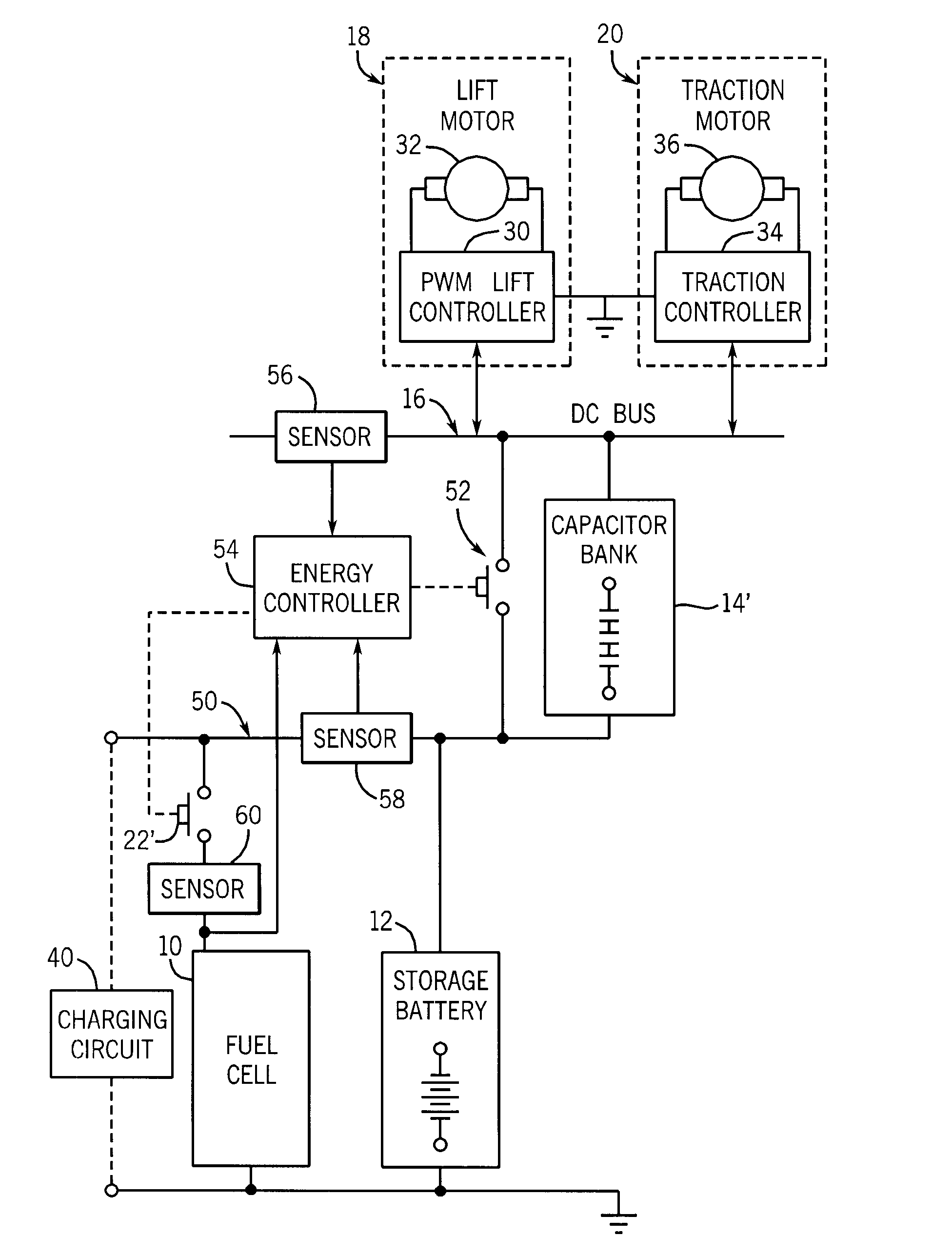
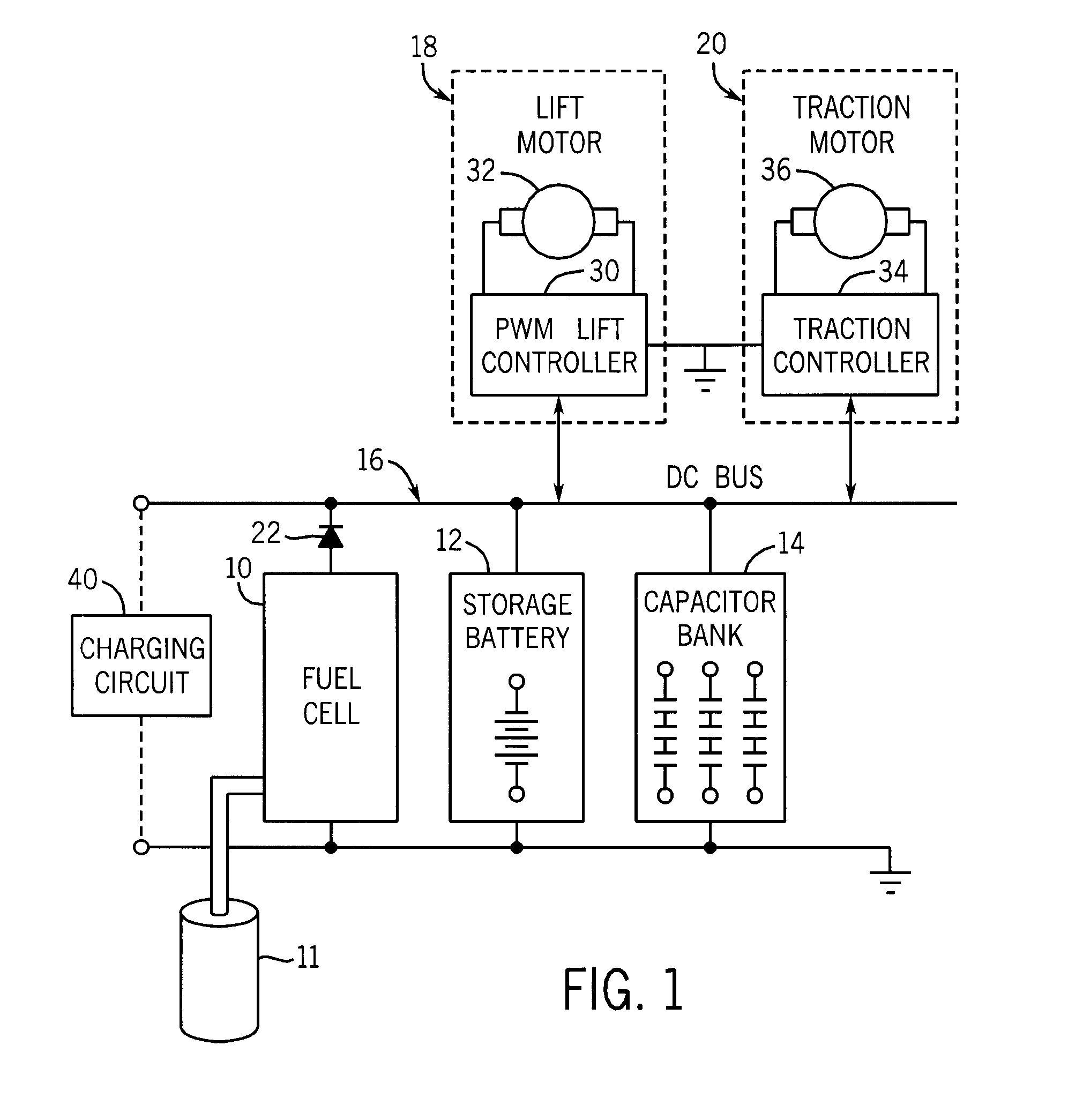
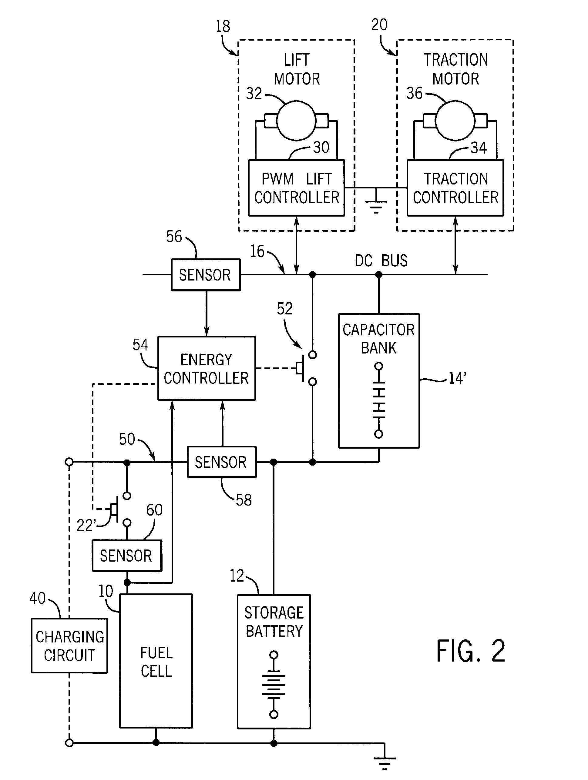
[0019]Referring particularly to FIG. 1, a first preferred embodime...


PUM


Abstract

A lift truck power source includes a hybrid power supply including a storage battery, a capacitor bank, and optionally a fuel cell. The capacitor bank stores power produced during regeneration by either the truck traction system or the lift system and delivers current when current demand exceeds that delivered by the fuel cell. The storage battery or fuel cell acts as a main power supply to deliver current at a rate sufficient to power the lift truck. When the fuel cell is the main power supply, the storage battery stores power during times when current demand is less than that delivered by the fuel cell and delivers current at times when current demand is greater than that delivered by the fuel cell. When the storage battery is the main power supply, the fuel cell supplements the power delivered by the storage battery, and can also recharge the storage battery.

Description

CROSS-REFERENCE TO RELATED APPLICATION[0001]This application claims priority to U.S. Provisional Application Ser. No. 60 / 728,689, filed Oct. 19, 2005, hereby incorporated by reference.BACKGROUND OF THE INVENTION[0002]The field of the invention is electric powered material handling vehicles, and more particularly lift trucks which perform lifting operations under a variety of operating conditions.[0003]Electric powered lift trucks employ large lead acid batteries to provide energy for their traction systems and their lift systems. The battery typically delivers from 24 to 48 volts to a DC bus and a traction system is powered from this bus to move the truck around the workplace under the control of an operator or a computer. The traction system can draw large currents from the DC bus during truck acceleration or when moving the truck up an incline, and it can regenerate current into the DC bus when “plugging” during truck deceleration or movement down an incline.[0004]The lift system ...

Claims


Application Information

Patent Timeline
Patent Type & Authority Patents(United States)
IPC IPC(8): B60K6/44
CPCB60L1/003B60L11/005B60L11/1851B60L11/1881B60L11/1887B66F9/07531B66F9/07572H02J7/34H02J7/345B60L1/20Y02T90/34B60L2200/40H02J2001/004Y02T10/7022Y02T10/705B60L50/40B60L58/10B60L58/30B60L58/40H02J2300/30Y02T90/40Y02T10/70
Inventor MCCABE, PAUL P.GREGORY, BRYCE A.DAY, RICHARD M.
Owner RAYMOND LTD
Why Eureka
Try Eureka