
Model-based active electronic damping for stepper motors

a stepper motor and electronic damping technology, applied in the direction of electric programme control, dynamo-electric converter control, instruments, etc., can solve the problem of mechanical resonance, the most unfavorable feature of the stepper motor, and the non-accumulative position error of the stepper system, etc. problem, to achieve the effect of accurately and efficiently modeling the behavior of the commercial stepper motor

Active Publication Date: 2010-06-08
ASM ASSEMBLY AUTOMATION LTD
View PDF8 Cites 9 Cited by
  • Summary
  • Abstract
  • Description
  • Claims
  • Application Information

AI Technical Summary

Benefits of technology

"The invention aims to accurately and efficiently model the behavior of a commercial stepper motor and provide a damping technique that can be applied to different models with varying configurations and operation speeds. The method involves identifying the force amplitudes and phase shifts of multiple harmonic detent torques, tuning the stepper motor with different current commands to minimize friction and resistive torque, and then injecting a compensating harmonic current derived from the force amplitudes and phase shifts of the detent torques into the current command during operation of the stepper motor to compensate for torque ripples. The technical effect of the invention is to improve the performance and stability of stepper motors in various applications."

Problems solved by technology

Furthermore, in normal working states, positional error is non-accumulative.
The cost of stepper systems is significantly lower than that of servo systems, mainly due to the removal of costly position feedback devices and complicated feedback control.
However, one of the most unfavorable features of stepper motors is mechanical resonance, especially at low speeds.
Resonance prevents the stepper motor from running steadily at certain speeds and reduces the usable torque.
It is not applicable to a particular motor model as such and cannot be applied to various configurations and speeds.
Nevertheless, prior art damping methods have their limitations.
For example, mechanical dampers will wear out with prolonged use.
Finally, electronic damping usually requires high order equations and complicated motor characteristics identification.

Method used


Image

  • Model-based active electronic damping for stepper motors
  • Model-based active electronic damping for stepper motors
  • Model-based active electronic damping for stepper motors

Examples


Embodiment Construction

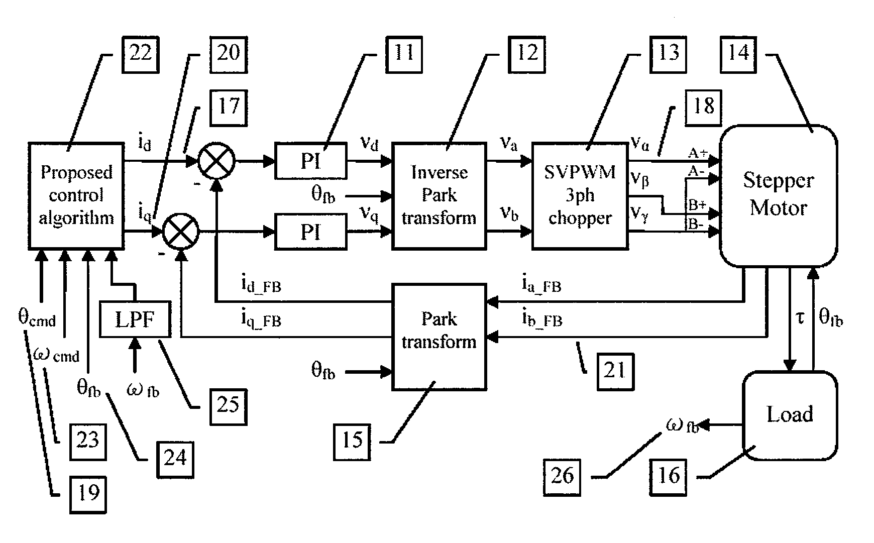
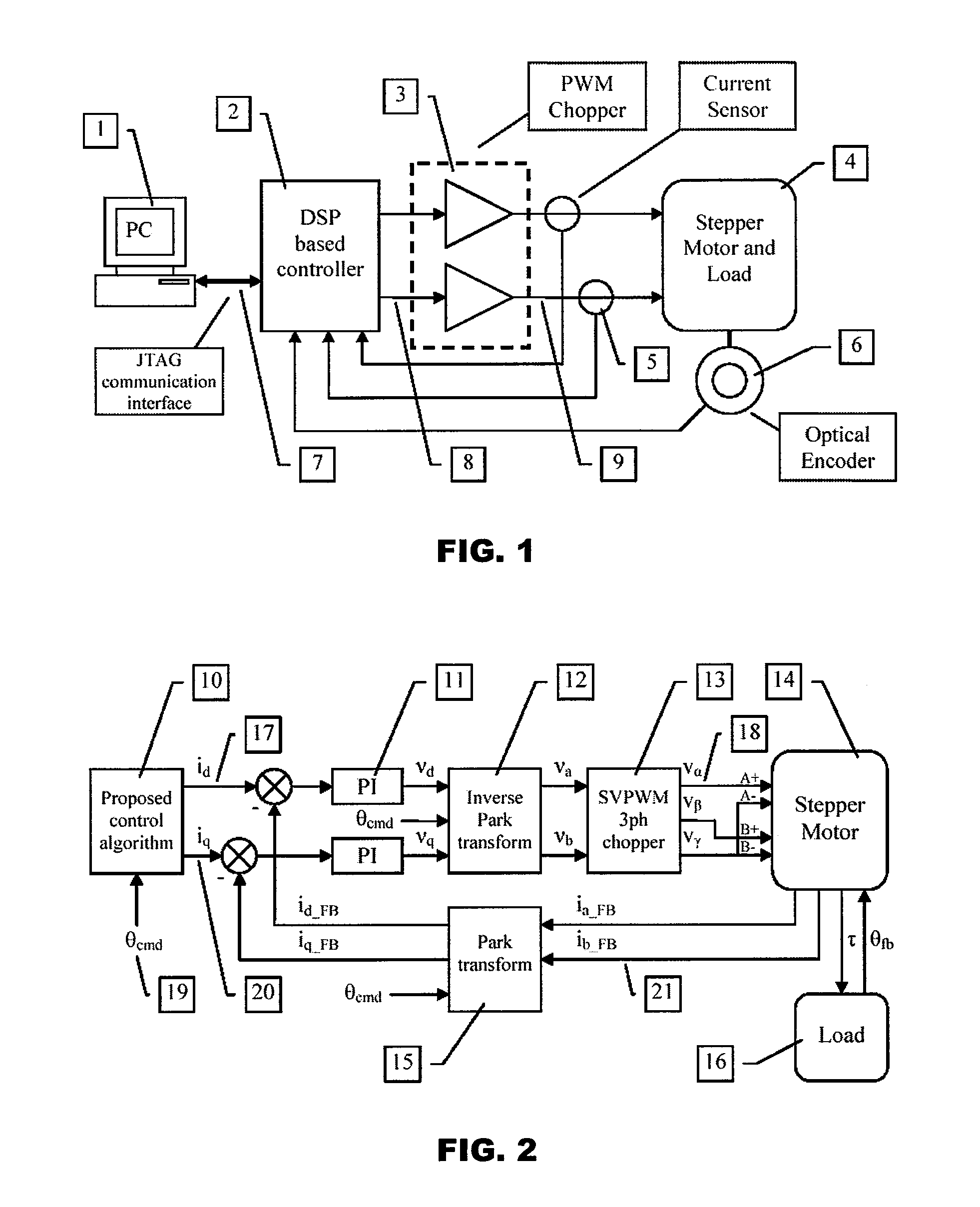
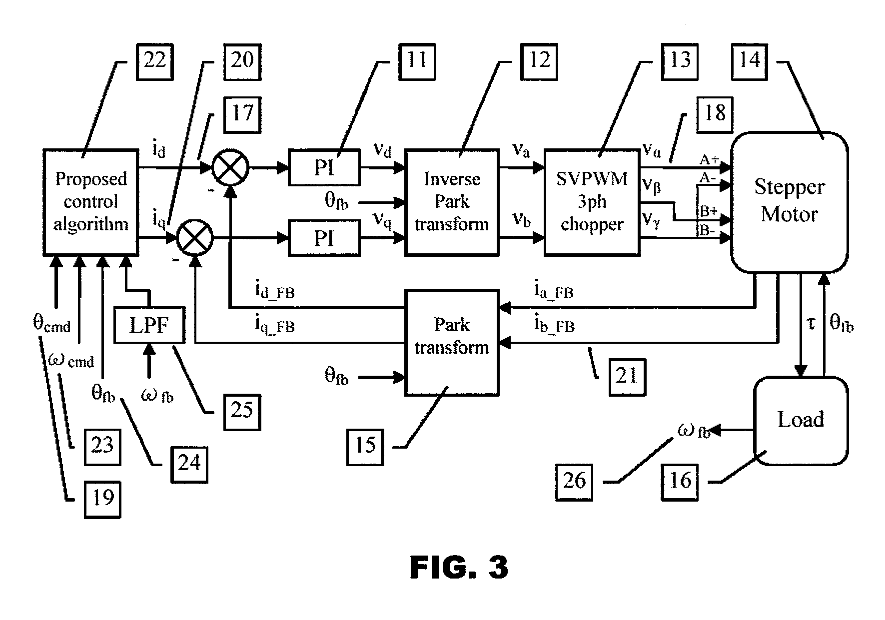
[0022]In the following description, it is assumed that the stepper motor used is optimized for sinusoidal microstep control. For open loop damping algorithms, it is assumed that fine microstepping (e.g. 1 / 64 or less) is used.

[0023]A simplified stepper motor model, including electrical dynamics and torque expression, is used most of the time for efficiency. The simplified stepper motor electrical dynamics and torque expressions are as follows:

[0024]ⅆiaⅆt=-RLo⁢ia+KmLo⁢ω⁢⁢sin⁢⁢(Nr⁢θ)+vaLo(1)ⅆibⅆt=-RLo⁢ib-KmLo⁢ω⁢⁢sin⁢⁢(Nr⁢θ)+vbLo(2)τ=Km⁡[-ia⁢sin⁡(Nr⁢θ)+ib⁢cos⁡(Nr⁢θ)]-Kd⁢⁢4⁢sin⁡(4⁢⁢Nr⁢θ)(3)[0025]where ia is the phase A current (A); ib is the phase B current (A); R is the winding resistance (Ω); Lo is the winding inductance (H); Km is the motor force constant or back e.m.f. constant (Nm / A); ω is the rotor angular velocity (rad / s); Nr is the number of pole pairs per revolution; θ is the rotor angular position (rad); va is the phase A voltage (V); and vb is the phase B voltage (V).

[0026]Wit...


PUM


Abstract

A method for damping vibrations in a stepper motor with micro-stepping control which comprises the steps of identifying the force amplitudes and phase shifts of multiple harmonic detent torques of the stepper motor, such as the first, second and fourth harmonic detent torques, and tuning the stepper motor with different current commands until minimum friction and resistive torque are obtained. Thereafter, a compensating harmonic current derived from said force amplitudes and phase shifts of the said multiple harmonic detent torques is injected into a current command during operation of the stepper motor to compensate for torque ripples.

Description

CROSS REFERENCE TO RELATED APPLICATION[0001]This application claims the benefit and priority of U.S. Provisional Application Ser. No. 60 / 866,634 filed on Nov. 21, 2006, and entitled MODEL-BASED ACTIVE ELECTRONIC DAMPING FOR STEPPER MOTORS, the disclosure of which is incorporated herein by reference.FIELD OF THE INVENTION[0002]The invention relates to stepper motors, and in particular, to the damping of vibrations in stepper motors during operation, especially mechanical resonance at low speeds.BACKGROUND AND PRIOR ART[0003]A stepper motor is a motor wherein its driveshaft rotates in small angular steps rather than continuously. For example, each angular step in a commercial stepper system may comprise rotation of 1.8°. The driveshaft can thus be moved to any position reliably by sending an appropriate number of step pulses. Although stepper motors are generally slower as compared to servo motors, stepper motor systems have several significant advantages and thus are very popular in ...

Claims


Application Information

Patent Timeline
Patent Type & Authority Patents(United States)
IPC IPC(8): G05B19/40
CPCH02P8/32
Inventor TSUI, WANG HAY KENNETHGAN, WAI CHUENTAM, SHING WAIOU, GANGNG, HON YU PETER
Owner ASM ASSEMBLY AUTOMATION LTD
Learn More