
Storage subsystem with embedded circuit for protecting against anomalies in power signal from host

a technology of embedded circuits and subsystems, applied in static storage, digital storage, instruments, etc., can solve problems such as circuit damage, data loss, data corruption, etc., and achieve the effect of preventing anomalies in power signal from being detected and protected from the hos

Active Publication Date: 2010-06-08
WESTERN DIGITAL TECH INC
View PDF32 Cites 244 Cited by
  • Summary
  • Abstract
  • Description
  • Claims
  • Application Information

AI Technical Summary

Benefits of technology

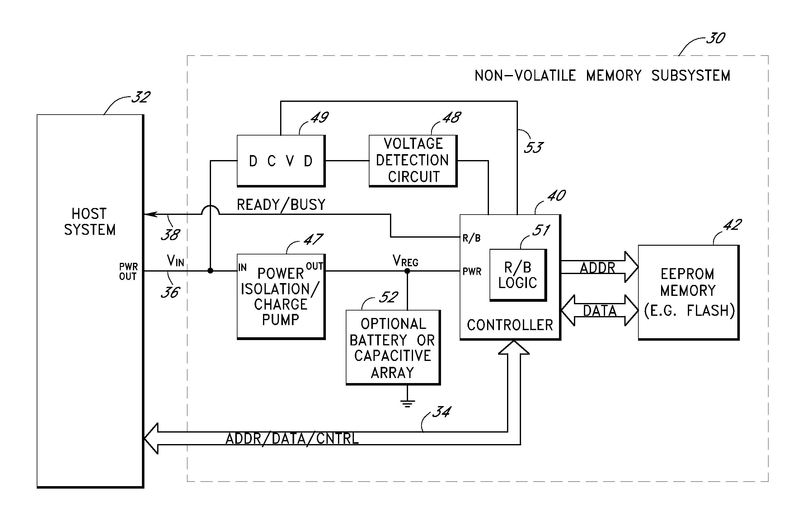
[0006]Embodiments of the disclosure provide a system and associated method for protecting a storage subsystem from irregularities in a power signal supplied by a host system. In one embodiment, the storage subsystem includes a charge pump circuit that receives a power signal from a host system, and generates a regulated power signal that is provided to the storage subsystem's controller (and possibly to other active components of the storage subsystem). When the power signal from the host is interrupted, the charge pump circuit acts as a backup power source such that the storage subsystem can continue to operate temporarily.
[0007]Embodiments recognize that during a power anomaly that power tends to flow from the storage subsystem to the host system. Thus, in addition to providing backup power, in certain embodiments the charge pump circuit is configured to provide power isolation for the storage subsystem. When the power signal from the host is interrupted, the power isolation circuitry prevents the reverse flow of current towards the host system from the charge pump or backup power source in order to increase the continued operation time of the storage subsystem.
[0008]The storage subsystem in the preferred embodiments also includes a voltage detection circuit that monitors the power signal from the host system to detect anomalies. The voltage detection circuit responds to detection of a power signal anomaly by asserting a busy signal to block the host system from sending instructions for write operations to the storage subsystem. An embodiment of the storage subsystem additionally comprises one or more digitally controlled voltage dividers (DCVD) (for example, digital voltage potentiometers) that are controlled by the controller, so that the voltage provided to the voltage detection circuit can be adjusted. The storage subsystem may thus be programmably adaptable to different voltage supplies from the host without requiring modifications in the hardware of the storage subsystem. By asserting the busy signal, the voltage detection circuit substantially ensures that backup power provided by the charge pump (and by the battery and / or capacitive array, if provided) will be sufficient for the controller to complete most or all outstanding operations. The likelihood that data will be lost as a result of the power signal anomaly is therefore significantly reduced.

Problems solved by technology

A significant problem in the area of storage subsystems relates to data loss, data corruption, and circuitry damage caused by interruptions and other irregularities in the power signal supplied by the host system.
For example, in the context of a flash memory subsystem, an unexpected power loss can cause a sector write operation to terminate prematurely, resulting in a mismatch between a sector's data and ECC portions.
In addition to losing the write data, the storage subsystem's controller may thereafter respond to the ECC mismatch condition by treating the sector as defective, and unnecessarily replacing the sector with a spare sector.
Incomplete sector write operations can also result in data loss and sector replacement in disk drives that store data on a rotating medium.
Other types of power signal anomalies, such as power surges and spikes, can additionally cause permanent damage to the circuitry of the storage subsystem.

Method used


Image

  • Storage subsystem with embedded circuit for protecting against anomalies in power signal from host
  • Storage subsystem with embedded circuit for protecting against anomalies in power signal from host
  • Storage subsystem with embedded circuit for protecting against anomalies in power signal from host

Examples


Embodiment Construction

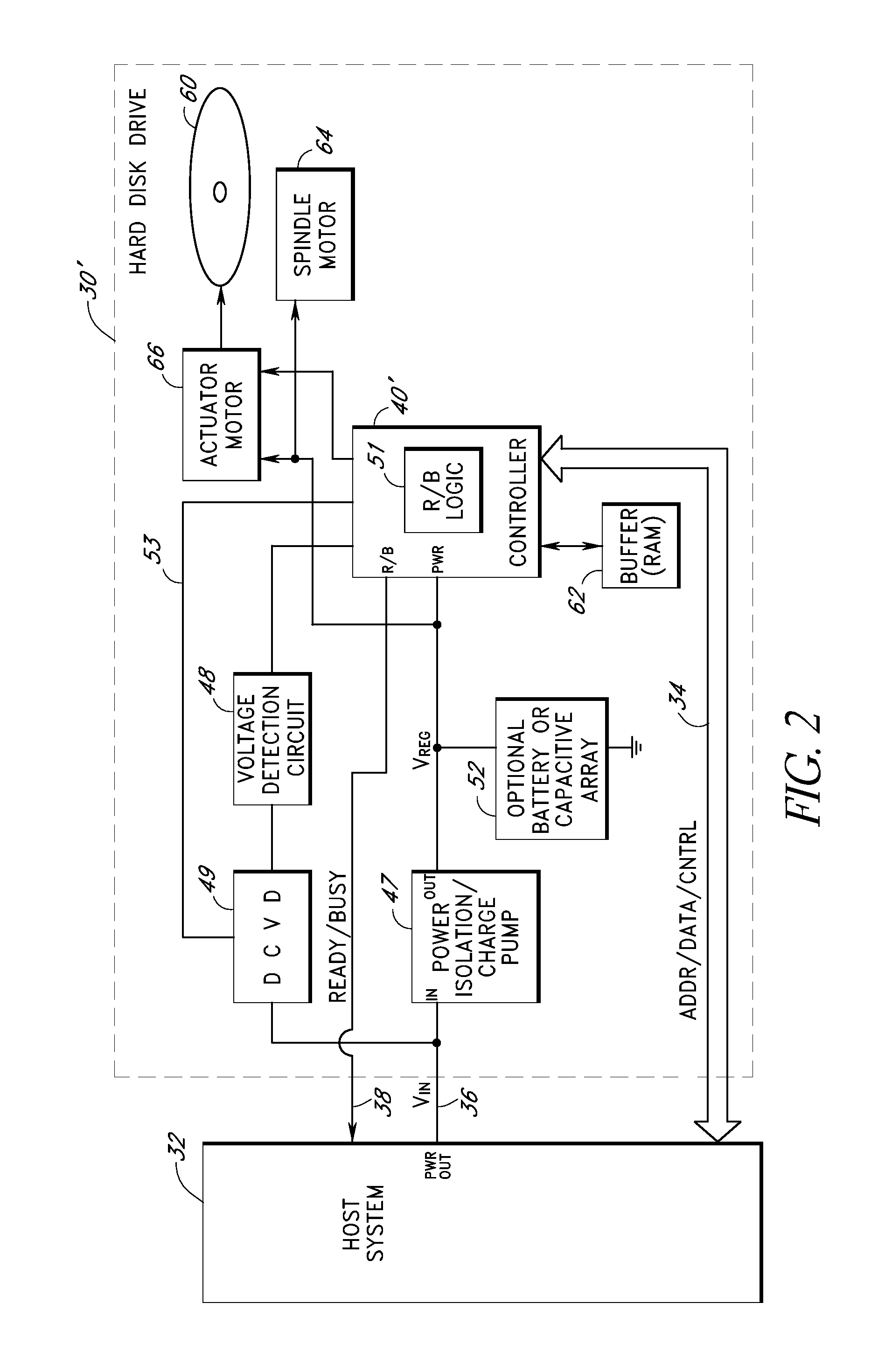
[0015]Embodiments may be embodied within a variety of different types of storage subsystems, including but not limited to non-volatile solid state memory cards (such as but not limited to those that comply with the CompactFlash, PCMCIA, SmartMedia, MultiMediaCard, SecureDigital and Memory Stick card specifications), volatile and non-volatile solid-state storage products in disk drive form factors, electro-mechanical disk drives, and volatile and non-volatile solid-state storage products in a variety of industry standard and custom form factors. No modifications to the host system are needed.

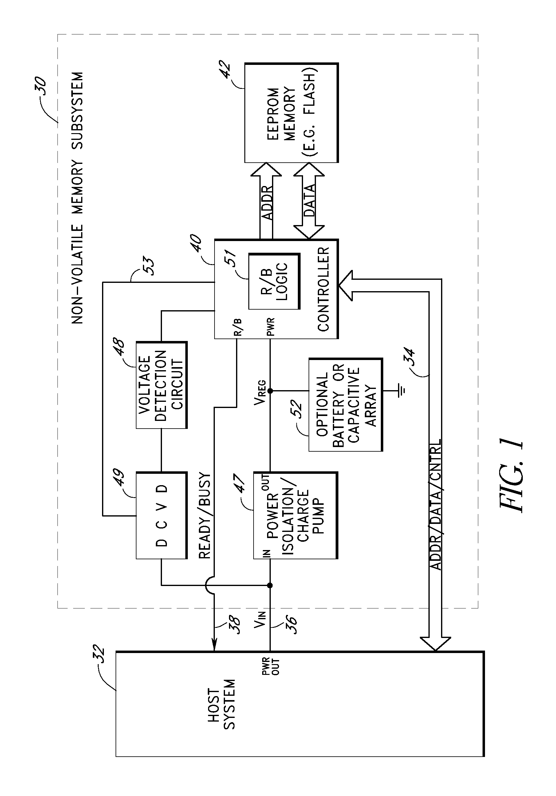
[0016]FIG. 1 illustrates a solid-state storage subsystem 30 according to one embodiment of the invention. The storage subsystem 30 may, for example, be a flash memory card that conforms to one of the aforementioned card specifications, although the invention is not so limited. The storage subsystem 30 plugs into a slot of, or otherwise attaches to, a host system 32 (hereinafter “host”). The host ...


PUM


Abstract

A storage subsystem includes a charge pump that receives a power signal from a host system, and generates a regulated power signal that is provided to the storage subsystem's controller. When the power signal from the host is interrupted, the charge pump additionally acts as a backup power supply to enable the storage subsystem to continue to operate temporarily, and power isolation circuitry in the storage subsystem prevents power from flowing back to the host system. The storage subsystem further includes a digitally programmable voltage detection circuit that accepts various supply voltages and asserts a busy signal to the controller when an anomaly in the power signal is detected. The controller includes logic circuitry that will block the host system from performing write operations to the storage subsystem either when the voltage detection circuit asserts a busy signal or when the controller is busy executing memory operation commands.

Description

RELATED APPLICATION[0001]This application relates to U.S. patent application Ser. No. 10 / 406,805, filed Apr. 3, 2003, entitled “Storage Subsystem with Embedded Circuit for Protecting Against Anomalies in Power Signal from Host,” which has been issued as U.S. Pat. No. 6,856,556, and U.S. patent application Ser. No. 11 / 037,728, filed Jan. 18, 2005, entitled “Storage Subsystem with Embedded Circuit for Protecting Against Anomalies in Power Signal from Host,” which has been issued as U.S. Pat. No. 7,126,857, the disclosures of which are hereby bodily incorporated by reference.BACKGROUND[0002]1. Technical Field[0003]The present invention relates to storage subsystems. More specifically, the present invention relates to circuits for protecting storage subsystems from damage and data loss caused by irregularities in a power signal.[0004]2. Description of the Related Art[0005]A significant problem in the area of storage subsystems relates to data loss, data corruption, and circuitry damage ...

Claims


Application Information

Patent Timeline
IPC IPC(8): G11C7/00
CPCG11C5/005G11C16/30G11C5/143G11C5/141
Inventor WALSTON, WESLEYDIGGS, MARK S.
Owner WESTERN DIGITAL TECH INC
Learn More