Clamping or spreading tool

a technology applied in the direction of mechanical control devices, instruments, manual control with single controlling member, etc., can solve the problems of unfavorable use of tools, so as to facilitate the handling of clamping and/or spreading tools, reduce weight, and facilitate manipulation

Active Publication Date: 2010-06-15
IRWIN IND TOOL CO
View PDF179 Cites 25 Cited by
  • Summary
  • Abstract
  • Description
  • Claims
  • Application Information

AI Technical Summary

Benefits of technology

[0008]A drive wheel adapted to be driven in rotation is provided for cooperation with the push or pull rod. As this rotatable drive wheel does not need a drive or acceleration path extending in longitudinal direction of the push or pull rod, the axial dimension of the clamping and/or spreading tool according to the invention is clearly reduced in comparison with known clamping and/or spreading tools having a corresponding mode of operation. Not only the weight is reduced as a consequence of the small dimensions but also the handling of the clamping and/or spreading tool is facilitated since its actuation, especially that of a stepping gear transmission is not obstructed by portions of the push or pull rod projecting far beyond the support. Especially when space is tight where a clamping or spreading tool is to be used and a handle of the stepping gear transmission is restricted, the clamping and/or spreading tool according to the invention is much ...

Problems solved by technology

It is a disadvantage of this quick-lock mechanism that much space is required to offer the quick-lock mechanism the path needed for unfolding the driving power stored.
As the compression spring assembly needs a long drive path for the driving power to unfold, clamping and/or spreading t...

Method used


Image

  • Clamping or spreading tool
  • Clamping or spreading tool
  • Clamping or spreading tool

Examples


Embodiment Construction

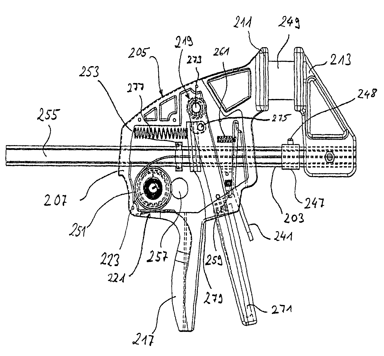
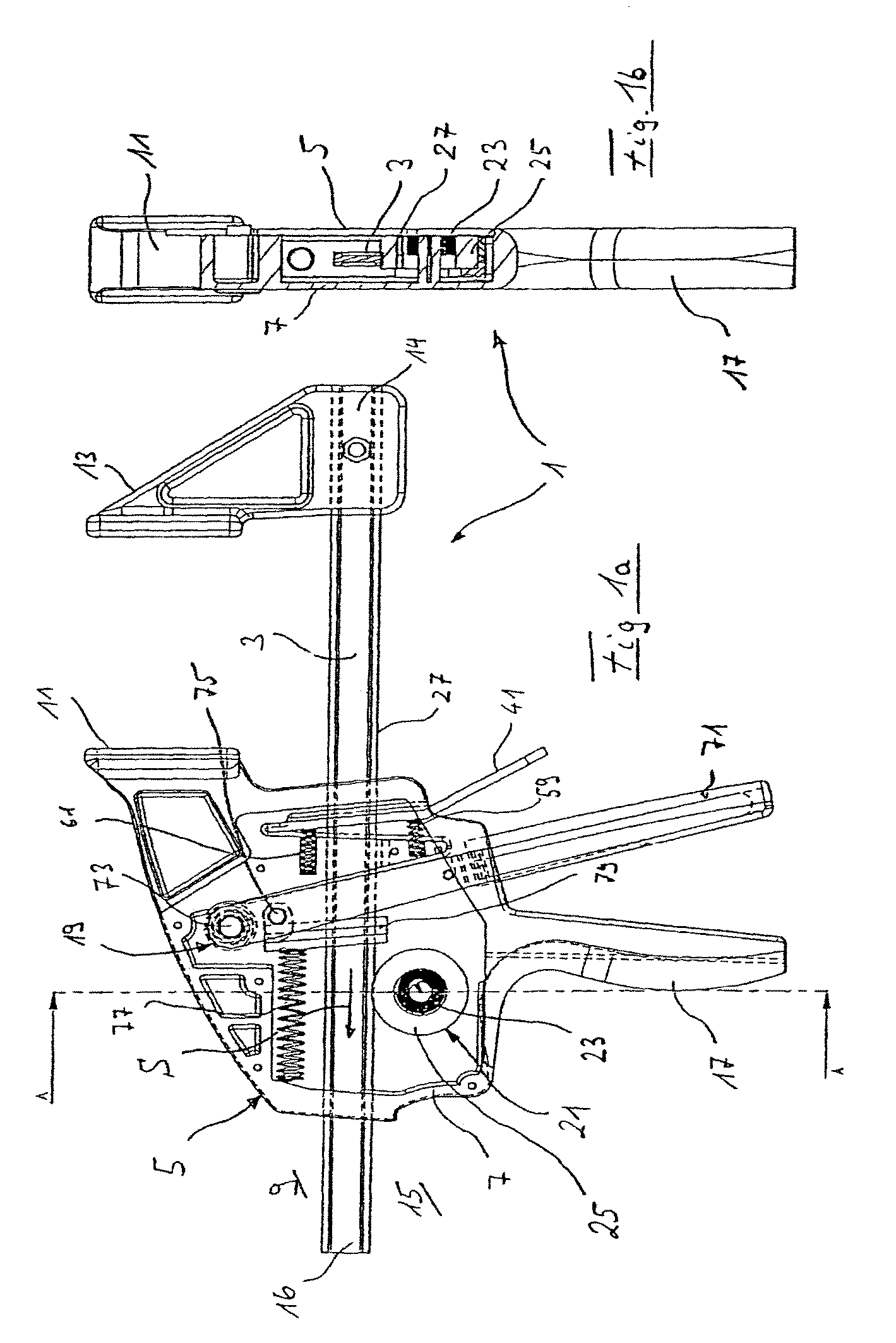
[0071]The preferred design of a clamping and / or spreading tool 1 illustrated in FIGS. 1a and 1b comprises a push or pull rod 3 movably supported on a support 5 for displacement in longitudinal direction of the rod. The support 5 comprises a closed casing 7, a fixed clamping jaw 11 being provided at the clamping side 9 of the push or pull rod 3, diametrically opposite a movable clamping jaw 13 which is removably attached to one end 14 of the push or pull rod 3.

[0072]FIG. 1a shows the clamping mode of the clamping and / or spreading tool 1. The clamping and / or spreading tool 1 will be in spreading mode when the movable jaw 13 is secured to the opposite end 16 of the push or pull rod 3.

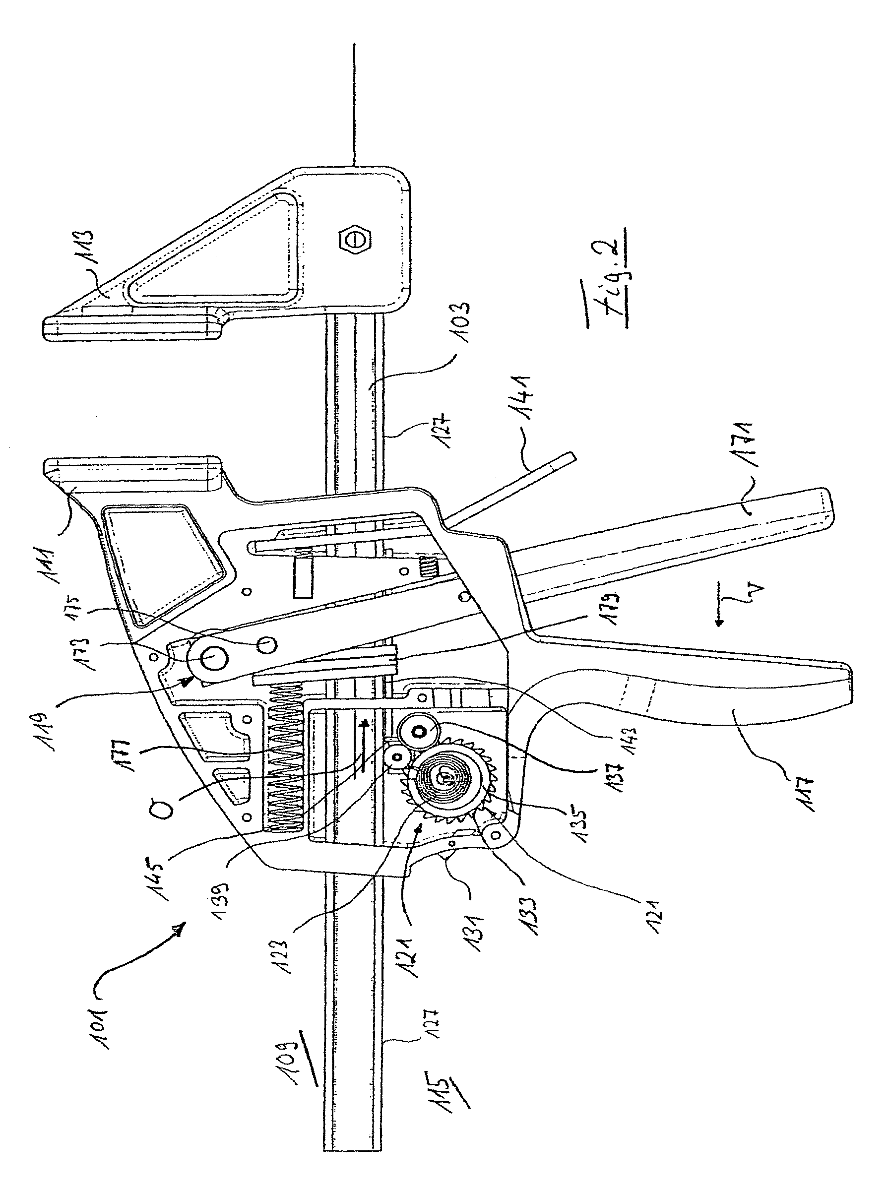
[0073]At the actuating side 15 of the push or pull rod 3, opposite the clamping side 9, a handle 17 is integrally fixed to the support 5 for the clamping and / or spreading tool to be held by one hand. In addition, the support 5 carries a stepping gear transmission 19, to be explained in greater detail below...


PUM


Abstract

A clamping and/or spreading tool comprises a drive for displacement of a push or pull rod to which a movable jaw is fixed with respect to a support carrying a stationary jaw in longitudinal direction of the push and pull rod, the drive comprising a torsion spring and being adapted to enter torque transmitting engagement with the push or pull rod for displacement of the same.

Description

RELATED APPLICATIONS[0001]This application is a continuation of and claims priority from U.S. patent application Ser. No. 10 / 576,091, filed on Apr. 11, 2006, which claims priority benefit of PCT EP / 2004 / 014179 filed on Dec. 13, 2004; DL 103 58 301.7 filed on Dec. 12, 2003; DL 103 58 296.7 filed on Dec. 12, 2003; DL 103 58 302.5 filed Dec. 12, 2003; DL 103 58 303.3 filed Dec. 12, 2003; DL 103 58 304.1 filed Dec. 12, 2003; and DL 103 58 291.6 filed Dec. 12, 2003, the entirety of which are hereby incorporated by reference.BACKGROUND[0002]1. Field of the Invention[0003]The invention relates to a clamping and / or spreading tool comprising a drive for displacement of a push or pull rod to which a movable jaw is fixed with respect to a support carrying a stationary jaw, in longitudinal direction of the push or pull rod.[0004]2. Description of the Related Art[0005]It is known to provide in particular clamping and / or spreading tools with a stepping gear transmission to cause stepwise approach...

Claims


Application Information

Patent Timeline
IPC IPC(8): B25B1/00B25B5/06F03G1/00F03G1/02
CPCB25B5/068F03G1/02F16C1/18Y10T74/20049Y10T29/49826
Inventor GEIER, MANFREDSTRAUSS, RALFREED, PHIL
Owner IRWIN IND TOOL CO
Why Eureka
Try Eureka