
Normal vector information generating device and normal vector information generating method

a technology of vector information and generating device, which is applied in the direction of optical radiation measurement, camera filters, instruments, etc., can solve the problems that the normal vector information cannot be generated for shadow areas accurately, and the normal vector information for shadow areas cannot be generated any more, etc., to achieve high precision, high practicality, and high refinement of images

Active Publication Date: 2010-06-15
PANASONIC CORP
View PDF16 Cites 11 Cited by
  • Summary
  • Abstract
  • Description
  • Claims
  • Application Information

AI Technical Summary

Benefits of technology

"The present invention provides a normal vector information generating device and method that can generate highly accurate normal vector information for shadow areas on the surface of an object. This is achieved by extracting attached shadow areas and cast shadow areas from an image of the object based on their polarization characteristics, and generating normal vector information that identifies a normal vector on the surface of the object in the attached shadow areas. This technique helps to improve the accuracy of image processing and enhance the quality of three-dimensional shape information obtained from mobile imaging devices."

Problems solved by technology

However, the technique of the above-mentioned Patent Reference 1 is directed to specular reflection only, and thus entails a problem that no normal vector information can be generated for shadow areas.
In addition, the technique of the above-mentioned Patent Reference 1 is directed to diffuse reflection only, and thus entails a problem that normal vector information cannot be generated accurately for areas such as shadow areas and specular reflection areas having reflection characteristics different from those of diffuse reflection.
In other words, each of the conventional techniques generates normal vector information using polarization, but entails a problem that normal vector information for shadow areas cannot be generated any more.
In the case where no normal vector information is generated for shadow areas, estimation accuracy of normal vector information is increased, but areas for which normal vector information can be estimated are limited.
In the opposite case where normal vector information for shadow areas is generated according to any of the conventional technique, the accuracy is extremely low.

Method used


Image

  • Normal vector information generating device and normal vector information generating method
  • Normal vector information generating device and normal vector information generating method
  • Normal vector information generating device and normal vector information generating method

Examples


embodiment 1

[0073]First, a description is given of the outline of a normal vector information generating device in Embodiment 1 of the present invention.

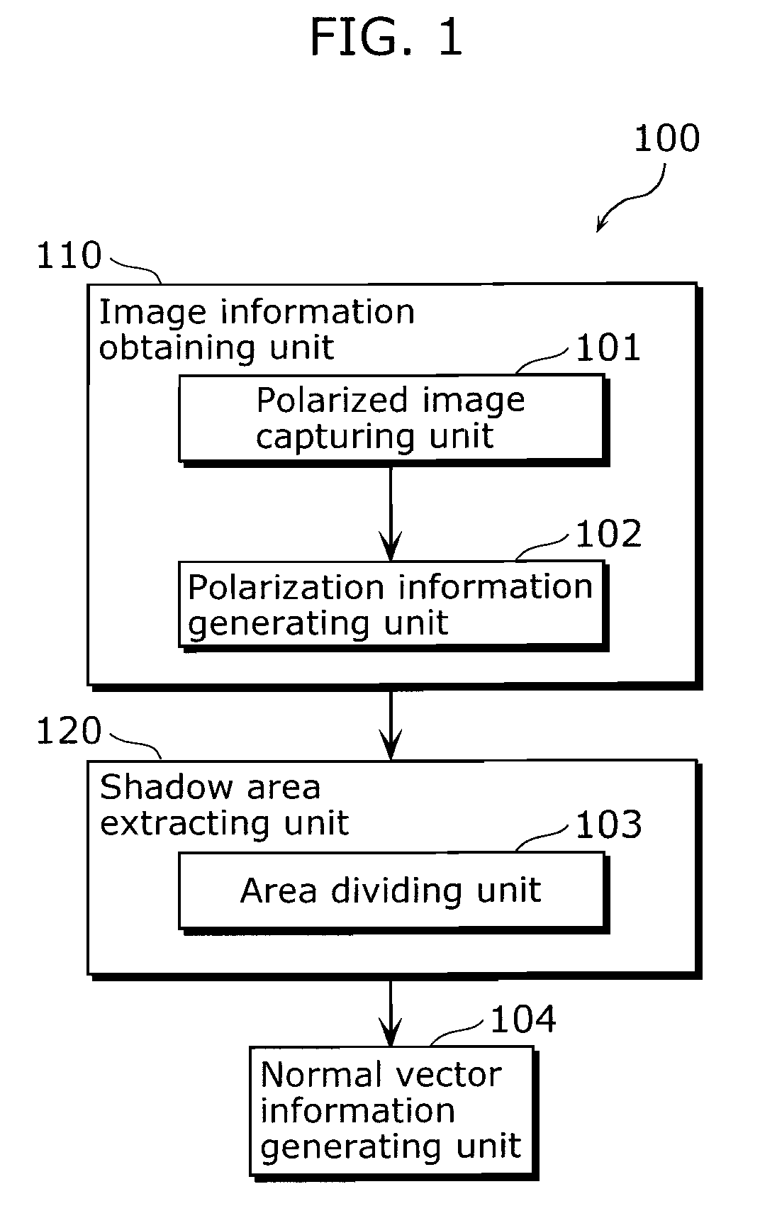
[0074]FIG. 1 is a functional block diagram showing the structure of a normal vector information generating device 100 in this Embodiment. This normal vector information generating device 100 is a device that generates normal vector information in the surface of an object, and includes an image information obtaining unit 110, a shadow area extracting unit 120, and a normal vector information generating unit 104.

[0075]The image information obtaining unit 110 is a processing unit for obtaining information related to an object image including luminance information about luminance of light from the object, and polarization information about polarization of light from the object, and includes a polarized image capturing unit 101 and a polarization information generating unit 102. It is to be noted that this image information obtaining unit 110 obtain...

embodiment 2

[0182]Next, a description is given of a normal vector information generating device in Embodiment 2 of the present invention.

[0183]FIG. 30 is a functional block diagram showing the structure of the normal vector information generating device 100b in this Embodiment. This normal vector information generating device 100b is a device for generating normal vector information on the surface of an object, and is characterized in that low luminance areas are classified into “attached shadow areas or low reflectance areas” and cast shadow areas. This normal vector information generating device 100b includes an area dividing unit 1031 and a normal vector information generating unit 1041 instead, which are slightly different in their functions from the area dividing unit 1031 and the normal vector information generating unit 1041 provided with the normal vector information generating device 100 in Embodiment 1. It is noted that the same structural elements as those of the normal vector inform...

embodiment 3

[0206]Next, a description is given of the normal vector information generating device in Embodiment 3 of the present invention.

[0207]FIG. 35 is a functional block diagram showing the structure of the normal vector information generating device 100c in this Embodiment. This normal vector information generating device 100c is a device for generating normal vector information of the surface of the object, and characterized by generating normal vector information only when accurate normal vector information can be generated. The normal vector information generating device 100c includes an imaging condition judging unit 106 in addition to the structure of the normal vector information generating device 100 shown in FIG. 1. It is to be noted that, in FIG. 35, the structural elements common with FIG. 1 are assigned with the same numerical references as those in FIG. 1, and detailed descriptions thereof are omitted.

[0208]The imaging condition judging unit 106 is a processing unit for judgin...


PUM


Abstract

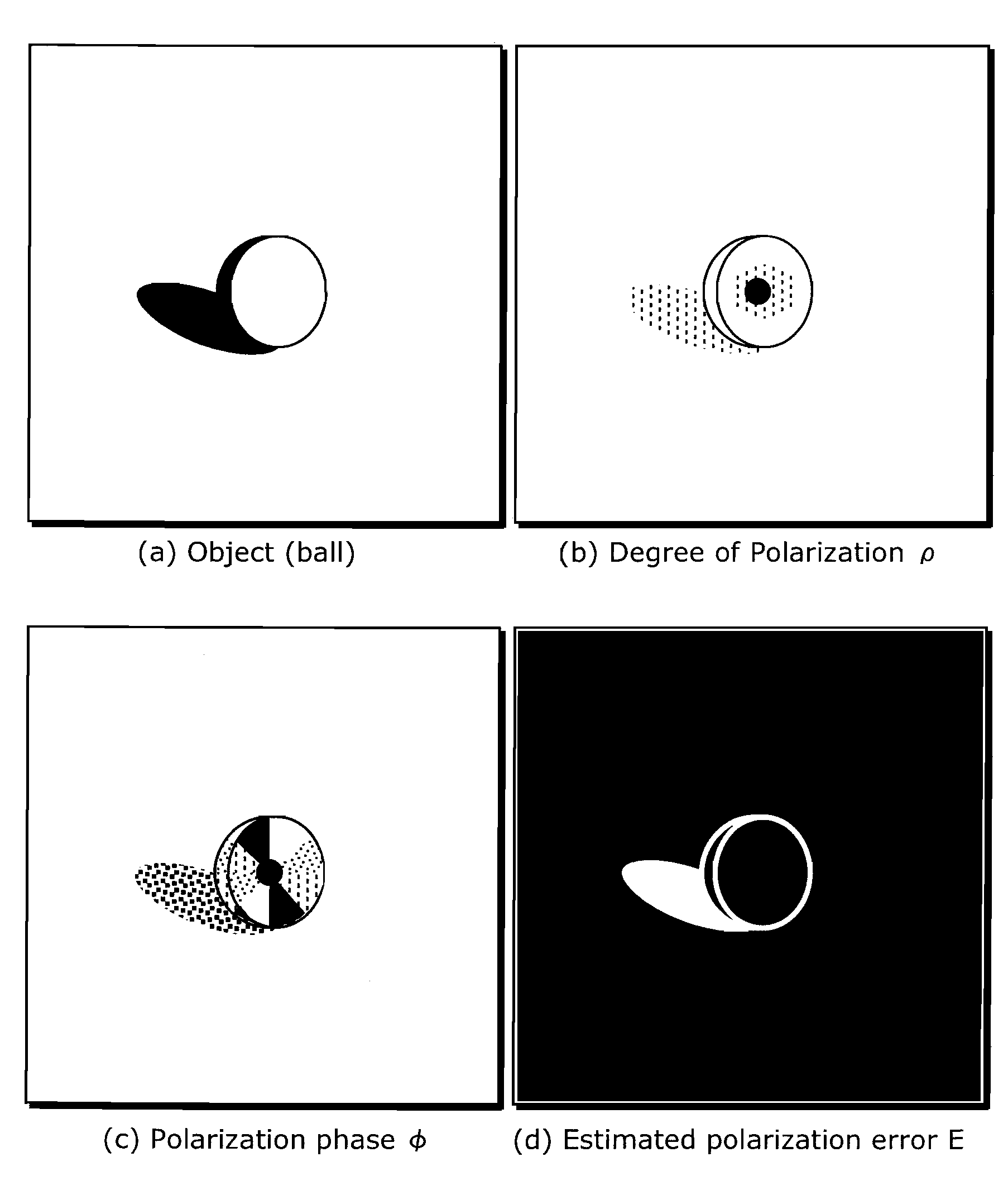
The normal vector information generating device generates normal vector information on the surface of an object, and includes: an image information obtaining unit obtaining information about an image of the object, the information including luminance information about luminance of light from the object and polarization information about polarization of the light; a shadow area extracting unit extracting an attached shadow area and a cast shadow area from the image based on the luminance information and the polarization information, the attached shadow area appearing on the surface of the object depending on an angle of incidence light, and the cast shadow area appearing on the surface of a material body when the light is blocked by the object; and a normal vector information generating unit generating normal vector information identifying a normal vector on the surface of the object in the attached shadow area using the polarization information.

Description

CROSS REFERENCE TO RELATED APPLICATION[0001]This is a continuation application of PCT application No. PCT / JP2008 / 002162 filed Aug. 7, 2008, designating the United States of America.BACKGROUND OF THE INVENTION[0002](1) Field of the Invention[0003]The present invention relates to a device which generates normal vector information on the surface of an object, and in particular to a device which generates normal vector information from a polarized image.[0004](2) Description of the Related Art[0005]It is said that mobile phones with a camera, digital cameras, digital movie cameras, and the like will be highly refined in the future as in the case of high definition televisions (HDTV), and miniaturization of these is being progressed to provide added values. However, it is conceivable that miniaturization of an optical system and imaging elements causes problems of limiting sensitivity and basic imaging performances such as the diffraction limit of a lens, and that high refinement will re...

Claims


Application Information

Patent Timeline
Patent Type & Authority Patents(United States)
IPC IPC(8): G06F17/00G06K9/34G06T1/00G06T15/00G06T15/50G06T15/60G01B11/26G03B7/28G03B11/00H04N5/225
CPCG01B11/002H04N5/232H04N5/2351G06T15/60G06T7/0081G03B35/26G06T7/0055G06T15/50G06T7/004G01S15/02G06T7/70G06T7/514G06T7/11H04N23/60H04N23/71
Inventor SATOKANAMORI, KATSUHIROSAITO, NATSUKINAKATA, MIKIYA
Owner PANASONIC CORP
Learn More