Pathogen and particle detector system and method

a detection system and a technology for pathogens and particles, applied in the field of system and method for detecting airborne or waterborne particles, can solve the problems of major difficulty in the instrumentation of laser particle counters, scattering signal must be extracted from incident illumination light source signal, and extremely dangerous weaponized anthrax spores, etc., to achieve backward-enhanced fluorescence

Inactive Publication Date: 2010-06-15
BIOVIGILANT SYST
View PDF161 Cites 43 Cited by
  • Summary
  • Abstract
  • Description
  • Claims
  • Application Information

AI Technical Summary

Problems solved by technology

Weaponized anthrax spores are extremely dangerous because they can gain passage into the human lungs.
One problem with existing detectors or particle counters which, are designed for detection of scattered light is that the scattering signal must be extracted from the incident illumination light source signal.
This feature has long caused major difficulty in the instrumentation of laser particle counters.
Conventionally designed laser particle counters employ costly and elaborate means to reduce the glare from the laser illumination source and to measure particle scattering against a large background noise, rendering the counters fragile and expensive.
Currently, conventionally designed laser particle counters are fragile and expensive, and unsuited to this application.
This is capable of detecting an aerosol concentration of five particles per liter of air, but involves expensive and delicate instruments.
These products are geared towards laboratory use and cost thousands of dollars for a single unit.
Thus, they are not suitable for a field-deployed detector, nor are they designed specifically for detection of biological warfare agents.
Although these devices are sufficient for the purpose of providing an alarm indication based on the presence of allergen particles, they are not suitable for field deployment and do not meet the more stringent requirements for a pathogen detector for detecting biological warfare agents.

Method used


Image

  • Pathogen and particle detector system and method
  • Pathogen and particle detector system and method
  • Pathogen and particle detector system and method

Examples


Embodiment Construction

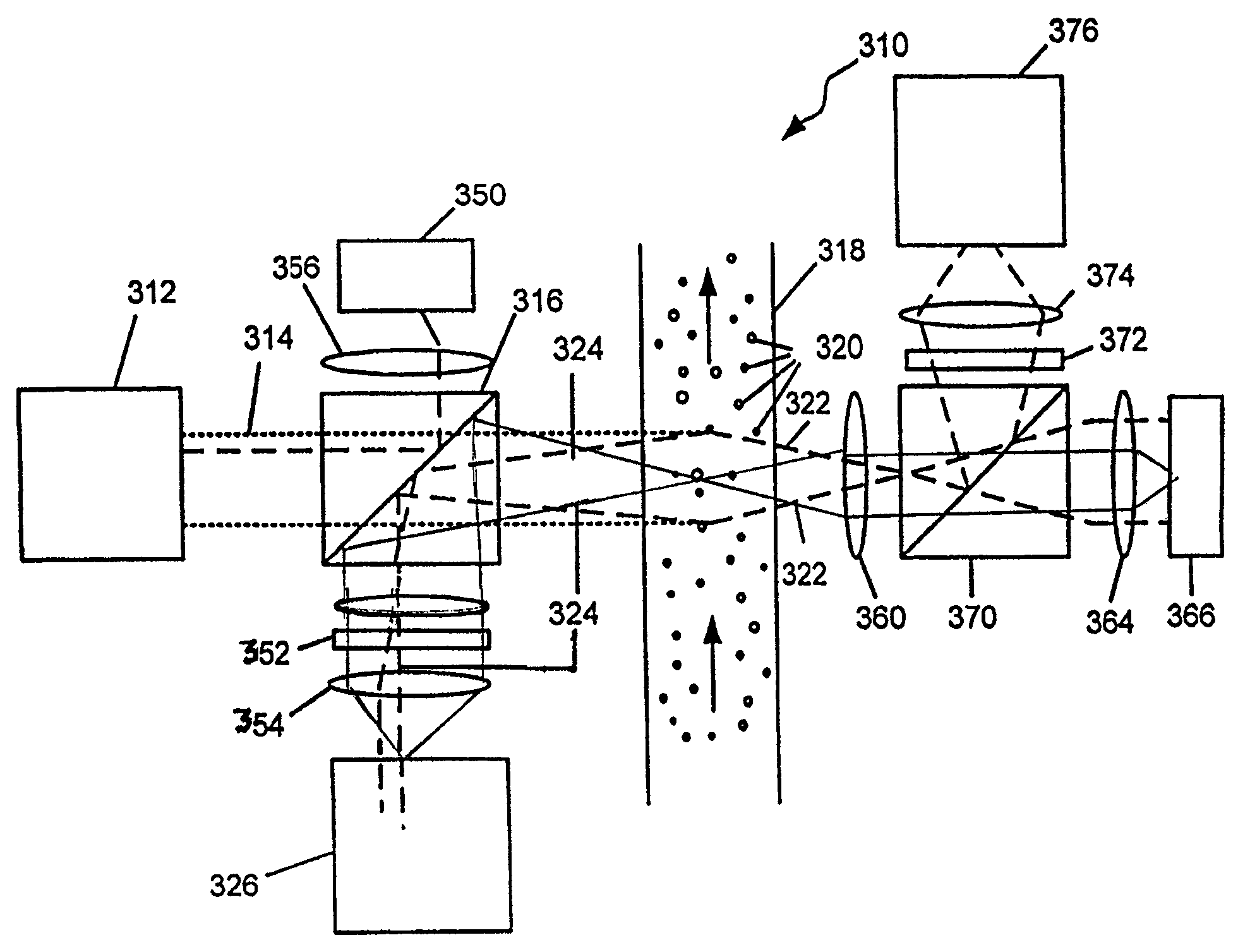
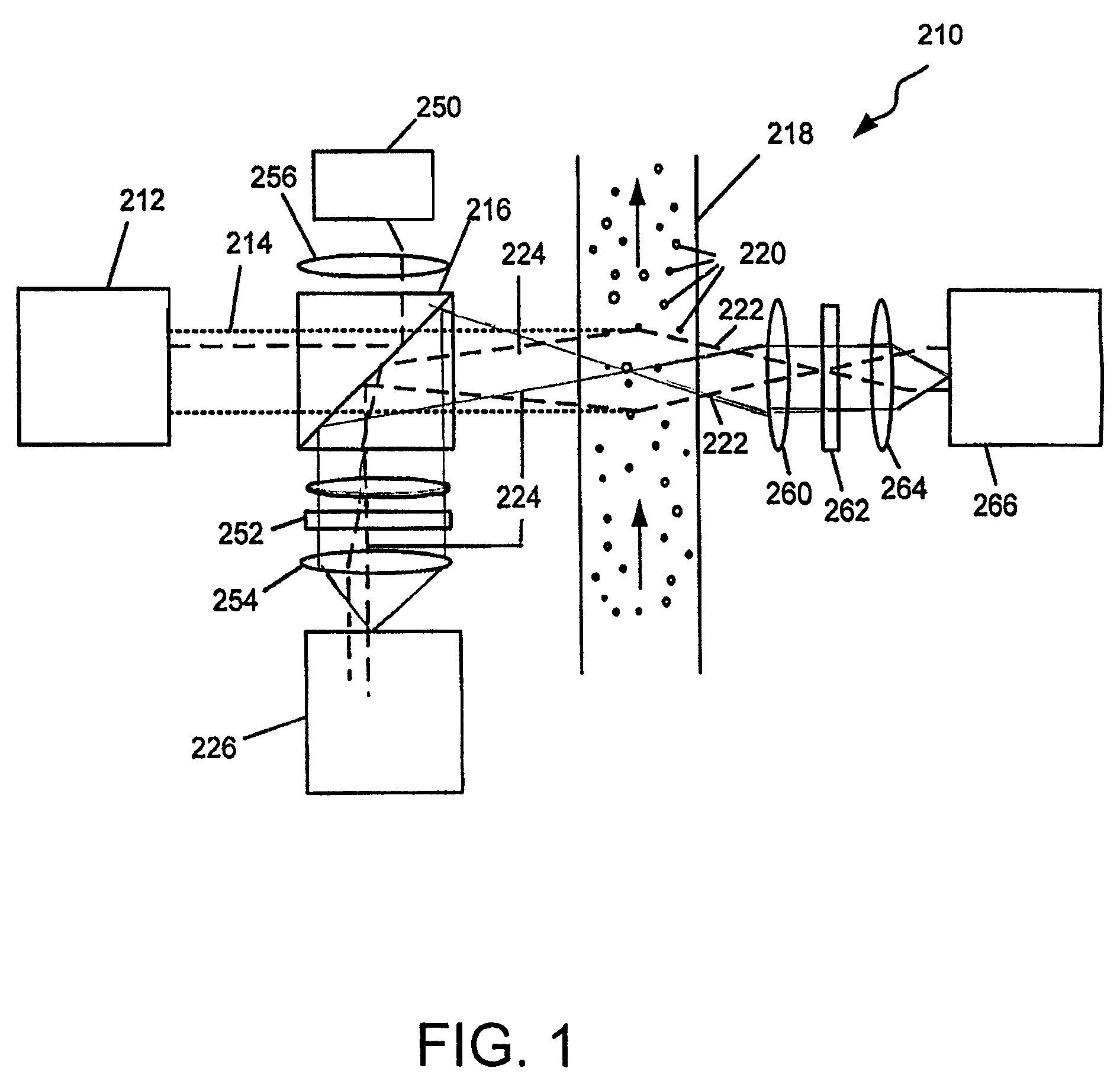
[0020]FIG. 1 is a representation of an optical system for a fluid particle detector system according to a first exemplary embodiment of the invention. This first exemplary embodiment of the system is particularly directed to detect airborne or waterborne bio-terrorist agents deliberately released by terrorists or others, but may also be used in civilian applications to detect harmful levels of other airborne or waterborne particles which may exist naturally such as mold or bacteria, or which may have been accidentally, inadvertently, naturally, or deliberately released, or other industrial applications such as the food and manufacturing industries, as well as clean room applications.

[0021]The term “fluid borne particles” as used herein means both airborne particles and waterborne particles.

[0022]The term “pathogen” as used herein refers to any airborne or waterborne particles, biological agent, or toxin, which could potentially harm or even kill humans exposed to such particles if p...


PUM

PropertyMeasurementUnit
wavelengthaaaaaaaaaa
source wavelengthaaaaaaaaaa

Abstract

The system includes an excitation source for providing a beam of electromagnetic radiation having a source wavelength. A first wavelength selective device is positioned to be impinged by the beam of electromagnetic radiation. The first wavelength selective device is constructed to transmit at least a portion of any radiation having the source wavelength and to reflect radiation of other wavelengths. A medium containing particles is positioned to be impinged by the beam of electromagnetic radiation. At least a portion of the beam of electromagnetic radiation becomes scattered within the medium, the scattered electromagnetic radiation including forward scattered electromagnetic radiation and backward scattered electromagnetic radiation. An optical detector is positioned to receive backward and / or forward scattered electromagnetic radiation.

Description

CROSS-REFERENCE TO RELATED APPLICATION[0001]This application claims priority to copending U.S. Provisional Application entitled, “Pathogen and Particle Detector System and Method,” having Ser. No. 60 / 700,008, filed Jul. 15, 2005, the contents of which are entirely incorporated herein by reference.FIELD OF THE INVENTION[0002]The present invention relates generally to a system and method for detecting airborne or waterborne particles, and more particularly to a system and method for detecting airborne or waterborne particles and classifying the detected particles by size. The invention has particular utility in detecting and classifying by size allergens and biological warfare agents and will be described in connection with such utility, although other utilities are contemplated.BACKGROUND OF THE INVENTION[0003]An urban terrorist attack involving release of biological warfare agents such as bacillus anthracis (anthrax) is presently a realistic concern. Weaponized anthrax spores are ex...

Claims


Application Information

Patent Timeline
Patent Type & Authority Patents(United States)
IPC IPC(8): G01N15/02
CPCG01N15/0205G01N2015/0088G01N2201/0624G01N15/02G01N21/47G01N33/53
Inventor MORRELL, MICHAELJIANG, JIAN-PING
Owner BIOVIGILANT SYST
Why Eureka
Try Eureka