Undercut saw

a saw and undercutting technology, applied in the field of power tools, can solve the problems of reducing the efficiency of the saw, and not allowing the saw to undercut the inside corner area, etc., and achieve the effect of reducing the tipping

Inactive Publication Date: 2010-06-22
CRAIN CUTTER
View PDF8 Cites 15 Cited by
  • Summary
  • Abstract
  • Description
  • Claims
  • Application Information

AI Technical Summary

Problems solved by technology

When installing flooring it is at times desirable to have the edges of the flooring extend underneath baseboards and / or walls.
Although it is possible to perform the undercutting by hand, this task is laborious and it is preferred to use a power tool.
Also, in order to undercut an inside corner, more than 180 degrees of the circumference of the blade must be exposed, and none of these devices have this design.
However this does not allow the saw to undercut inside corner areas because the side of the blade guard still contacts the wall, and because less than 180 degrees of the circular saw blade is exposed for undercutting.
However, this long back end makes the tool more difficult to use in tight spaces, such as closets.
Furthermore, the drive system consisting of a spindle gear perpendicular to an armature gear is not effective for generating low RPMs or high torque.
Thus this type of saw can tend to bog down and overheat in operation.
In addition to the problem of cutting the inside corner, all of the prior devices have less than ideal handles.
In addition, the position of the handles tends to make the user put downward pressure on the tool, making the desired sideways motion less comfortable.
For the undercut saw in FIG. 2, the handle position is also poor.
This requires that in use the user bend one wrist back at an uncomfortable angle.
This again reduces the efficiency of the tool.
However this adjustable positioning makes the handle prone to rotate forward, especially as force on the handle is exerted during cutting.
In addition, the handle is gripped from the top, which is a less than efficient position for the desired sideways movement of the tool in operation.
During use of the device housing 2 is heated by motor 3 and becomes uncomfortable as a gripping surface.
Finally, the handles 6, 7 of FIG. 4 are also awkward, requiring a user to grip ball like structures.
This tends to put downward pressure on the tool, which makes the desired sideways motion of the tool along a wall more difficult.
Thus as the user attempts to apply pushing force on handle 7 the sensation is one of having one's wrist bent further backwards, which is quite uncomfortable.
Thus, the hand is pushing forward while also pulling a switch backward at the same time, which is awkward.
Moreover, the added tension in the wrist created by the pulling action of the trigger finger creates even greater discomfort in the wrist.
Because the thumb is not on the housing, it does not assist in gripping, which is not effective for transferring force.
This makes shutting off the device during an emergency take more time.
This is not ideal during an emergency, especially if the user has lost some control of the tool.
Many features which are preferred in the design of an undercutting saw make it likely to tip over, which is a safety hazard.
Lastly, in a device with a motor that employs parallel drive and spindle shafts, the motor is taller and thereby generates more leverage that tends to cause tipping.

Method used


Image

  • Undercut saw
  • Undercut saw
  • Undercut saw

Examples


Embodiment Construction

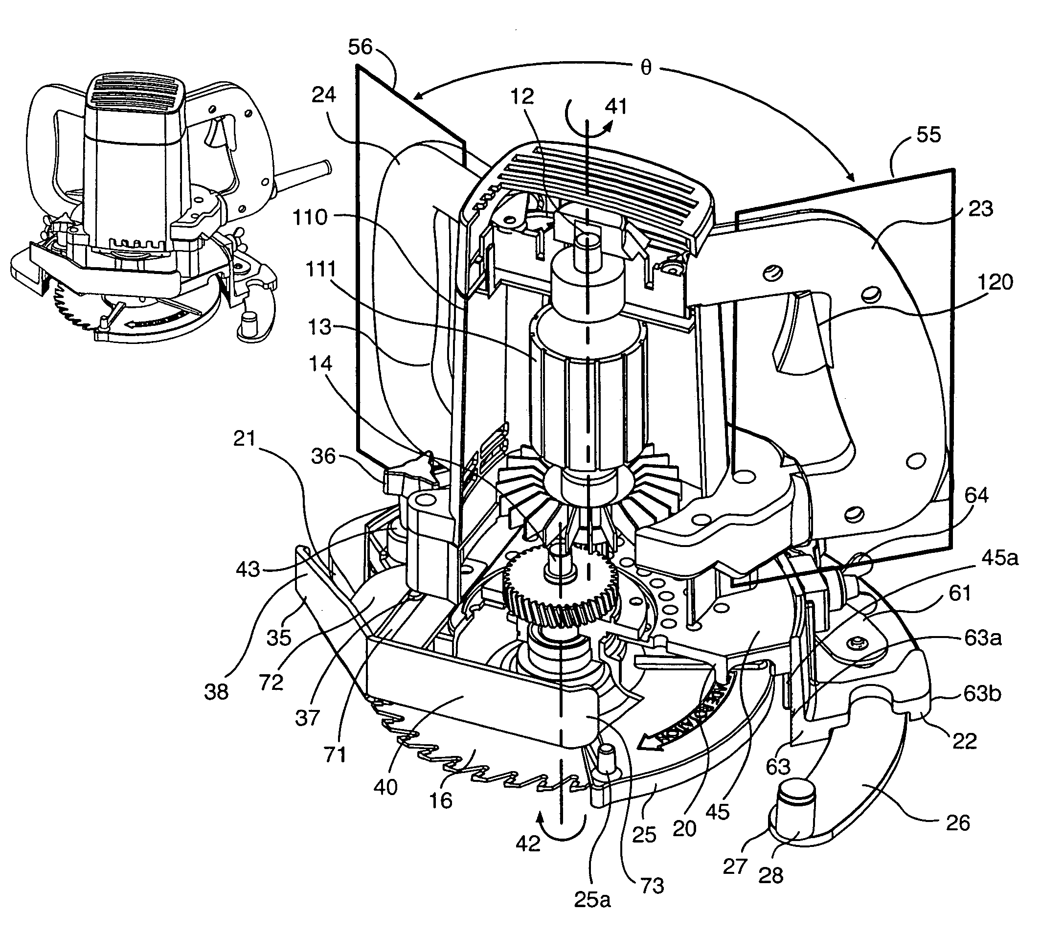
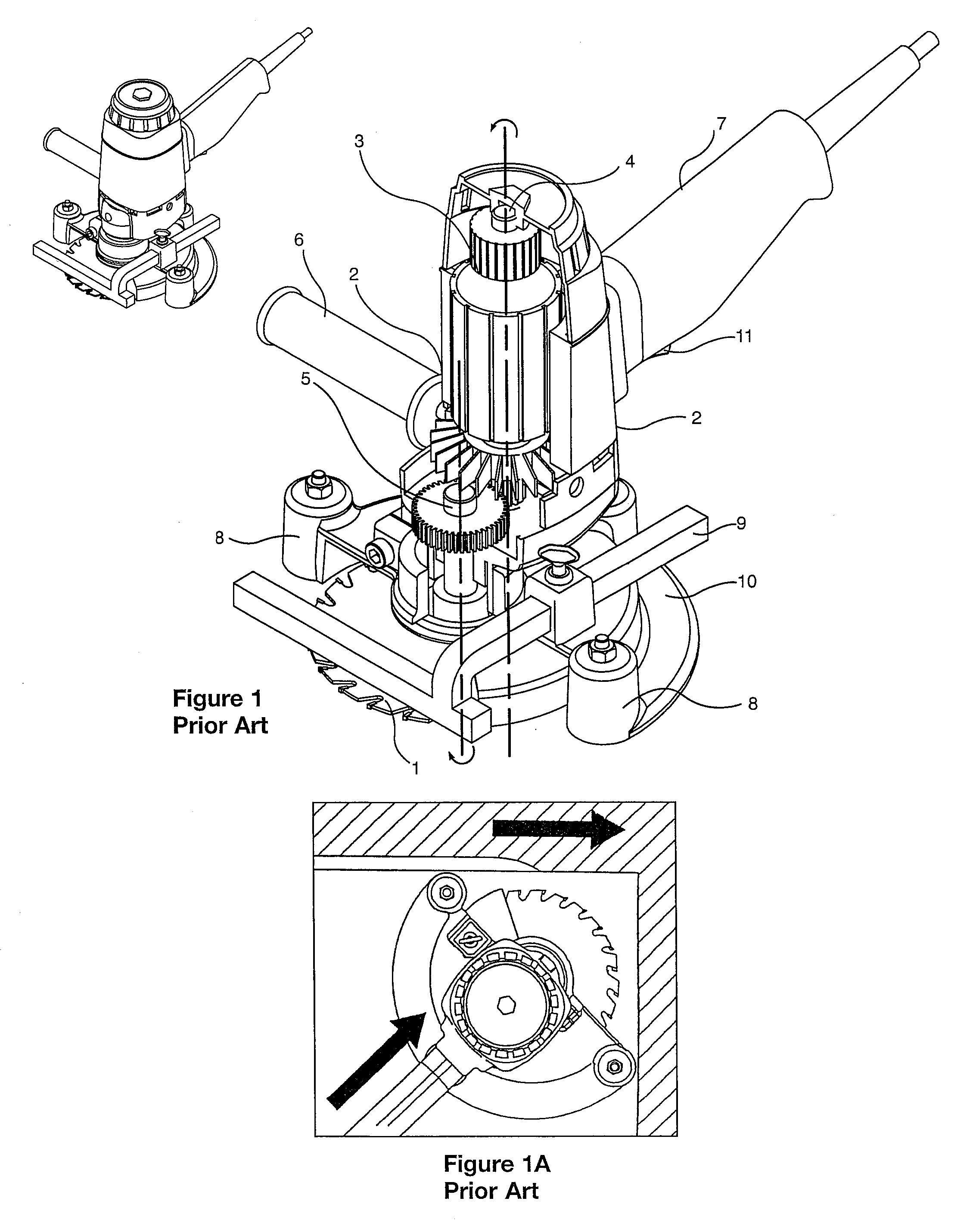
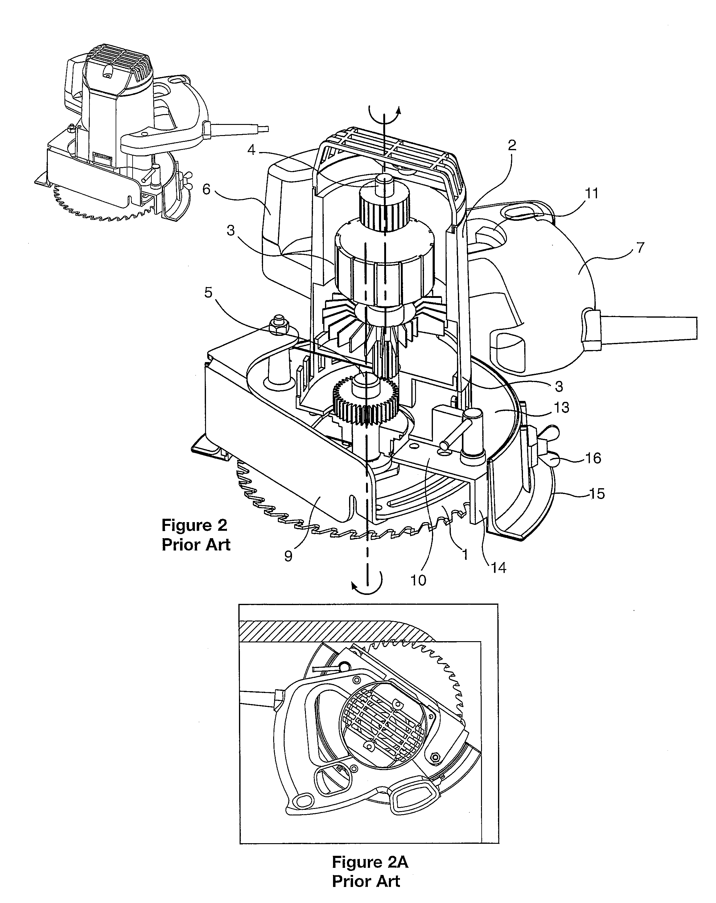
[0047]The present invention has a number of new and useful features not currently available in undercutting saws. Stability is important for undercut saws. If the saw in use tips forward or backward, it can result in damage to the wall or floor and possibly injure the user. Two design features, when utilized, further add to this instability. One is the incorporation of a fixed blade guard housing exposing a portion of the circular saw blade that is greater than 180 degrees of the saw blade's circumference. The fixed blade guard acts as the stable base for the saw. Reducing this circumferential area of the fixed blade guard makes the tool more likely to tip. The use of parallel armature and spindle shafts further leads to the adoption of a taller tool that is more likely to tip. A first aspect of the present invention utilizes a stabilization bar that extends from the fixed blade guard. This stabilization bar may be used in any undercut saw regardless of the mechanism in which the dr...


PUM

PropertyMeasurementUnit
angleaaaaaaaaaa
angleaaaaaaaaaa
angleaaaaaaaaaa

Abstract

An undercut saw including a housing, a motor within said housing, a drive shaft rotated by said motor, and a blade mount mechanically linked to said shaft such that a circular saw blade mounted on said mount is rotated when the motor rotates the drive shaft. A fixed blade guard circumscribes a portion of the blade and allows selectable height adjustment of the blade. A stabilization bar on the fixed blade guard may be extended to make the device more stable. On the underside of the fixed blade guard a dust channel allows dust to be swept by the rotating blade into a dust port. The dust channel allows positioning of the dust port away from the leading edges of the fixed blade guard.

Description

CROSS-REFERENCE TO RELATED APPLICATION[0001]This application claims priority from U.S. Provisional application No. 60 / 623,321, filed Oct. 29, 2004.TECHNICAL FIELD[0002]This invention relates generally to power tools and more specifically to undercut saws.BACKGROUND OF THE INVENTION[0003]When installing flooring it is at times desirable to have the edges of the flooring extend underneath baseboards and / or walls. To fit the flooring into this area, the wall and / or baseboard needs to be undercut at a specific height to allow the flooring to be installed underneath. Although it is possible to perform the undercutting by hand, this task is laborious and it is preferred to use a power tool. An undercut saw may be specifically designed to undercut a wall for the installation of flooring. This requires a specialized tool.[0004]FIGS. 1 and 2 show two available undercut saw designs. FIG. 1 illustrates one of the earliest models, designed by Crain Cutter Company (Milpitas, Calif.). In this too...

Claims


Application Information

Patent Timeline
Patent Type & Authority Patents(United States)
IPC IPC(8): B23D45/00
CPCB23D59/006B27B9/02B27B5/08Y10T83/207Y10T83/7734Y10T83/7793Y10T83/855
Inventor CRAIN, LANCE D.NGUYEN, TAN D.
Owner CRAIN CUTTER
Why Eureka
Try Eureka