
Compact, low pressure-drop shock-driven combustor

a combustor and shock-driven technology, applied in the direction of engine starters, turbine/propulsion engine ignition, intermittent jet plants, etc., can solve the problems of prohibitively long run-up length due to the constraint of relatively high pressure drop of cyclic detonation devices, and achieve the effect of enhancing a combustion process and efficient creation of cyclic detonations

Active Publication Date: 2010-06-22
GENERAL ELECTRIC CO
View PDF13 Cites 36 Cited by
  • Summary
  • Abstract
  • Description
  • Claims
  • Application Information

AI Technical Summary

Benefits of technology

"The patent describes a system and method for efficiently creating cyclic detonations to generate power. The system includes a first initiator chamber and a main chamber coupled together, with an initial connection section that enhances the combustion process. The main chamber is configured to generate a main wave that travels upstream and downstream within the chamber when the first initiator chamber is located outside the main chamber. The system also includes an oxidizer supply system and a fuel supply system to provide the necessary materials for the combustion process. The method involves generating an initial wave within the first initiator chamber, configuring the main wave to travel upstream and downstream within the main chamber, and outputting thrust generated from the initial wave. Overall, the system and method provide a more efficient and effective way to generate power through cyclic detonations."

Problems solved by technology

However, the obstacles for cyclic detonation devices have a relatively high pressure drop and are cooled.
For practical propulsion systems, the run-up length due to this constraint can be prohibitively long.

Method used


Image

  • Compact, low pressure-drop shock-driven combustor
  • Compact, low pressure-drop shock-driven combustor
  • Compact, low pressure-drop shock-driven combustor

Examples


Embodiment Construction

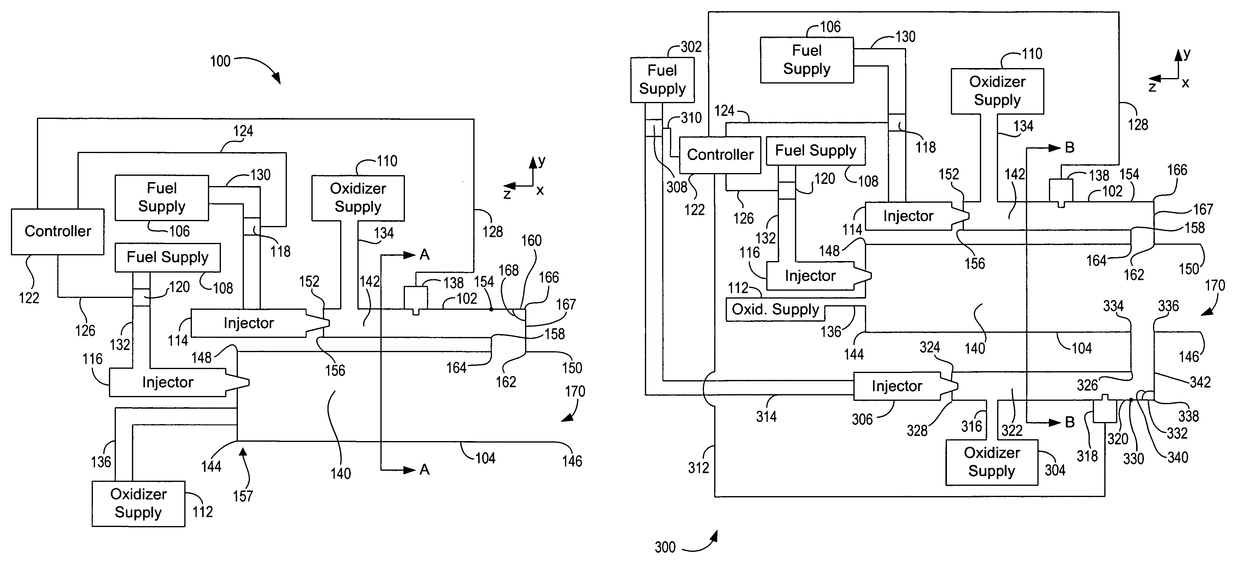
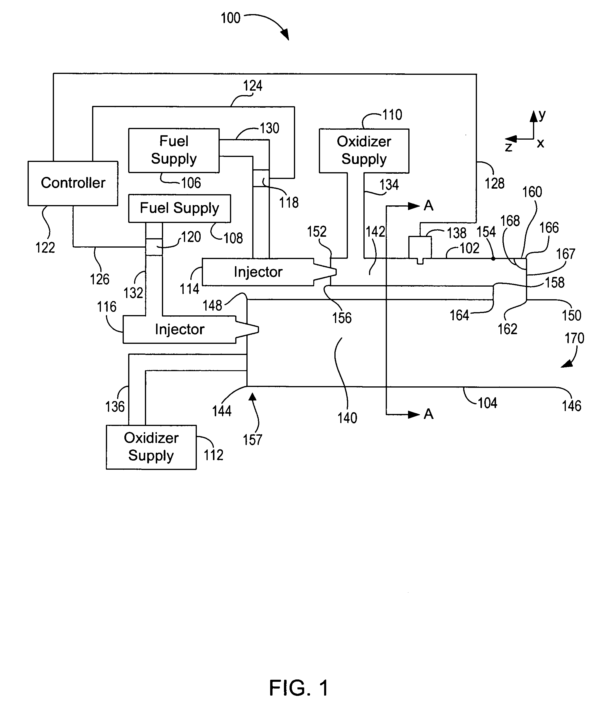
[0016]A shock-to-detonation Transition (SDT) can be used to initiate detonations in a large combustion chamber by transitioning a supersonic flame or a detonation wave, which is generated in an ignitor with a small diameter, into a larger main chamber filled with fuel-oxidizer mixture. In the SDT process, one or more initiators generate a supersonic flame or a detonation wave using a deflagration-to-detonation transition (DDT) process, which is then transitioned to a larger chamber using a carefully positioned reflecting and shock-focusing surface. The resulting supersonic flame or detonation wave propagates through the larger main chamber consuming a fuel-air mixture within the larger main chamber. In general, the SDT process makes detonation transition from a smaller chamber to a larger chamber possible, and a run-up time and a run-up length used for this transition are much smaller when compared to the DDT process occurring in a chamber.

[0017]A pulse detonation combustor (PDC) in...


PUM


Abstract

A system for efficiently creating cyclic detonations is provided. The system includes at least a first initiator chamber configured to generate an initial wave, at least one main chamber coupled to the first initiator chamber. The main chamber is configured to generate a main wave and to output products of supersonic combustion. The products are generated within the main chamber. The main chamber is configured to enable the main wave to travel upstream and downstream within the main chamber when the first initiator chamber is located outside the main chamber. The system further includes an initial connection section located between the first initiator chamber and the main chamber that enhances a combustion process via shock focusing and shock reflection.

Description

BACKGROUND OF THE INVENTION[0001]This invention relates generally to cyclic pulsed detonation combustors (PDCs) and more particularly, to a compact, low pressure drop transition of detonations with small initiation devices.[0002]In a generalized pulse detonation combustor, fuel and oxidizer (e.g., oxygen-containing gas such as air) are admitted to an elongated combustion chamber at an upstream inlet end of the pulse detonation combustor. An igniter (spark or plasma ignitor) is used to initiate a combustion process within the pulse detonation combustor. Following a successful transition to detonation, a detonation wave propagates toward an outlet of the pulse detonation combustor at supersonic speed causing a substantial combustion of the fuel and oxidizer mixture before the mixture can be substantially driven from the outlet. A result of the combustion is to rapidly elevate pressure within the pulse detonation combustor before a substantial amount of gas can escape through the outle...

Claims


Application Information

Patent Timeline
Patent Type & Authority Patents(United States)
IPC IPC(8): F02K5/02F02K7/00
CPCF02K7/02
Inventor KENYON, ROSS HARTLEYTANGIRALA, VENKAT ESWARLUHINCKLEY, KEVIN MICHAELDEAN, ANTHONY JOHNMYERS, STEPHEN DANIEL
Owner GENERAL ELECTRIC CO
Learn More