
Adhesion testing device

a technology of adhesion testing and test device, which is applied in the field of material testing, can solve the problems of excessive shock to the load cell in the device, difficult to consistently control the pull rate, and many of the adhesion test devices currently available, and achieves the effects of simple, portable, and rugged battery operated devices

Inactive Publication Date: 2010-06-22
LOCKHEED MARTIN CORP
View PDF4 Cites 4 Cited by
  • Summary
  • Abstract
  • Description
  • Claims
  • Application Information

AI Technical Summary

Benefits of technology

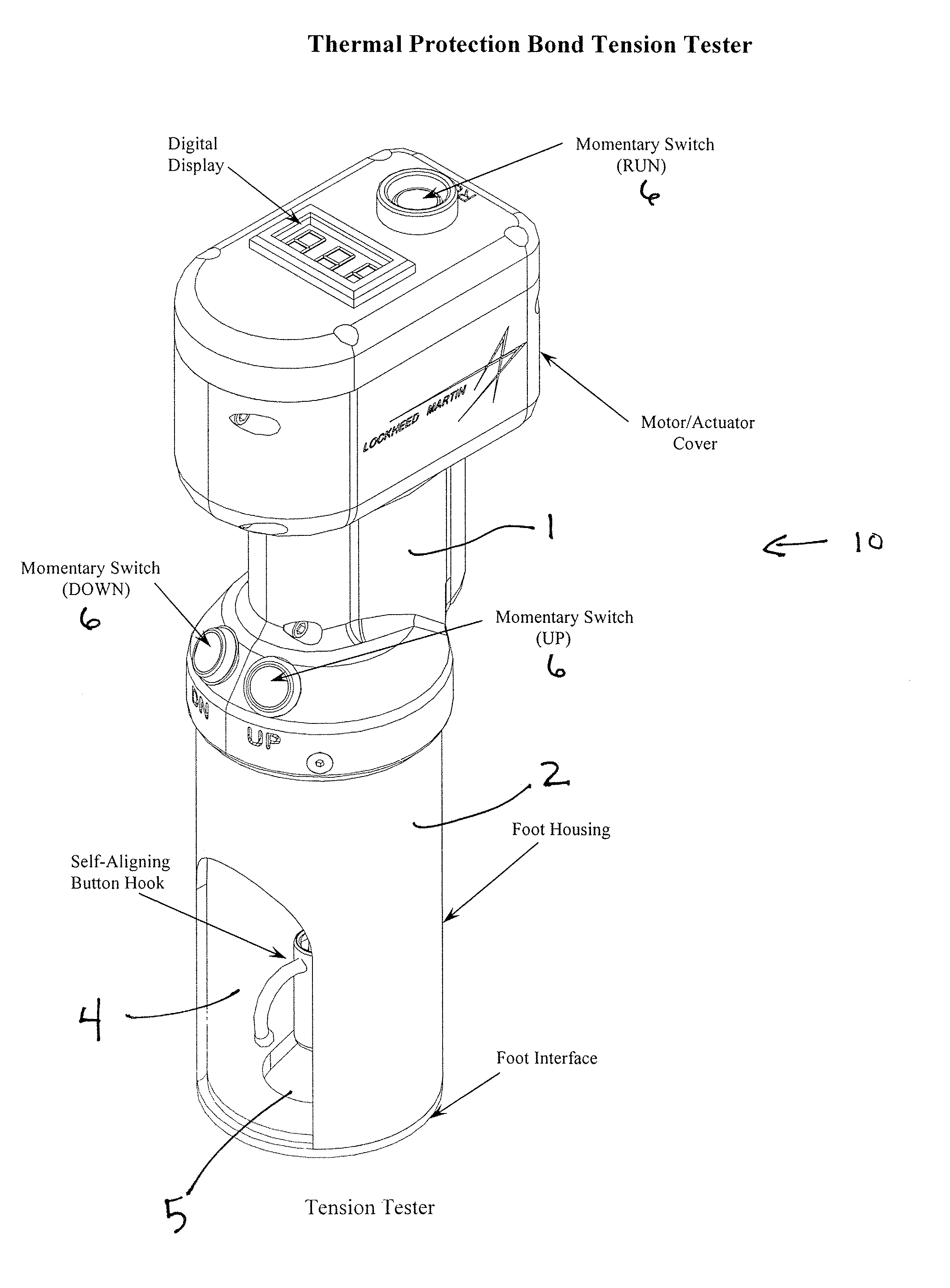
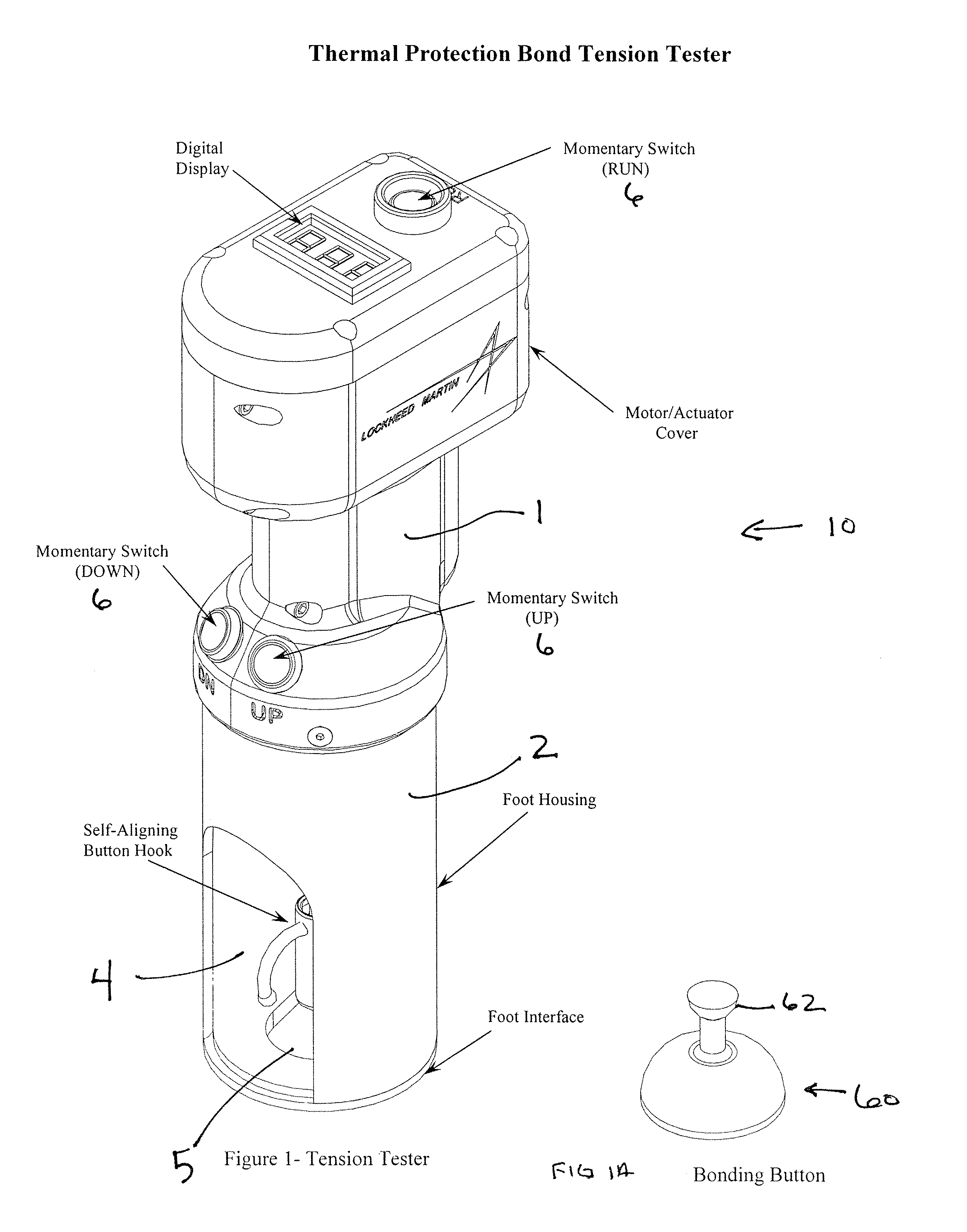
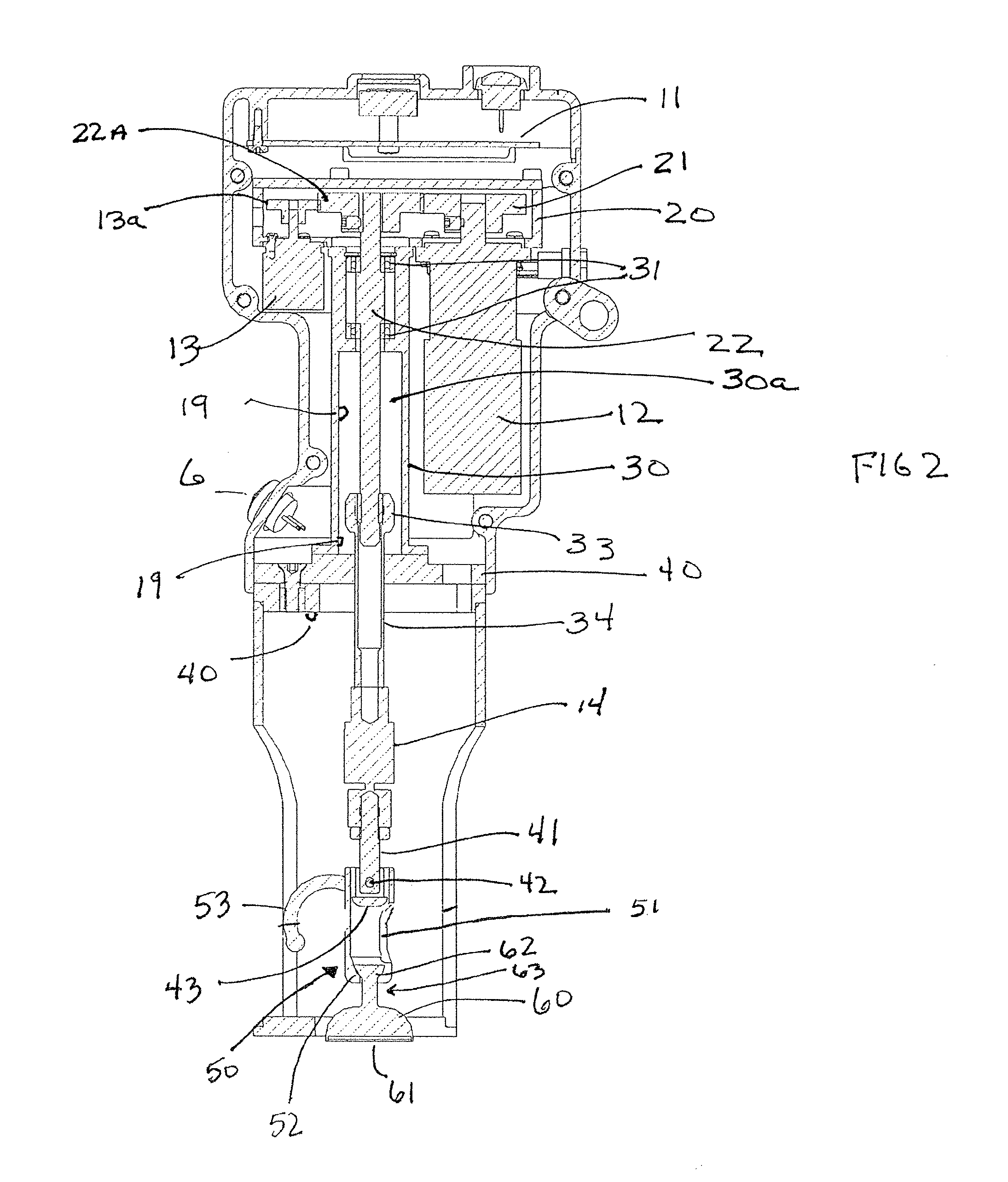
[0005]The present invention provides a testing apparatus and method for testing the adhesion of a coating to a surface. The invention also includes an improved testing button or dolly for use with the testing apparatus and a self aligning button hook or dolly interface on the testing apparatus. According to preferred forms, the apparatus and method of the present invention are simple, portable, battery operated rugged, and inexpensive to manufacture and use, are readily adaptable to a wide variety of uses, and provide effective and accurate testing results. The device includes a linear actuator driven by an electric motor coupled to the actuator through a gearbox and a rotatable shaft. The electronics for the device are contained in the head section of the device. At the contact end of the device, is positioned a self aligning button hook, attached below the load cell located on the actuator shaft.

Problems solved by technology

Many of the coating adhesion test devices that are currently available have been found to be unwieldy in use and unduly complex and expensive, especially for routine testing in the field.
Many current testing devices use pneumatic actuators to apply the pulling or tensile force, but it has been found that it is difficult to consistently control the rate of pull for pneumatic controlled devices, and can create excessive shock to the load cell in the devices.

Method used


Image

  • Adhesion testing device
  • Adhesion testing device
  • Adhesion testing device

Examples


Embodiment Construction

[0012]Referring now to the drawing figures, wherein like reference numerals represent like parts throughout, the testing device and method, and the test dolly of the present invention will now be described with reference to preferred embodiments. It is to be understood that the embodiments described and depicted herein are intended as examples to provide an understanding of the invention, but that the invention is not limited to the specific embodiments described.

[0013]A first preferred embodiment of the testing device 10 of the present invention is shown in FIGS. 1-4. The device 10 preferably comprises a hollow body 3 having a head section 1 and a tail section 2. Positioned on top of the head section is a visual indicator 15, and a control buttons 6. The tail section 2 is either open at bottom 5, or has an open slot in a bottom panel. Tail section 2 also has a side slot 4 to allow access to the button engagement section 43 later described. The components disposed within the substan...


PUM

PropertyMeasurementUnit
diameteraaaaaaaaaa
diameteraaaaaaaaaa
adhesionaaaaaaaaaa

Abstract

The present invention provides a testing apparatus and method for testing the adhesion of a coating to a surface. The invention also includes an improved testing button or dolly for use with the testing apparatus and a self aligning button hook or dolly interface on the testing apparatus. According to preferred forms, the apparatus and method of the present invention are simple, portable, battery operated rugged, and inexpensive to manufacture and use, are readily adaptable to a wide variety of uses, and provide effective and accurate testing results. The device includes a linear actuator driven by an electric motor coupled to the actuator through a gearbox and a rotatable shaft. The electronics for the device are contained in the head section of the device. At the contact end of the device, is positioned a self aligning button hook, attached below the load cell located on the actuator shaft.

Description

FUNDING[0001]The U.S. Government has certain rights to this application and invention pursuant to the terms of Contract No. 453631 82500 32200 awarded by the National Aeronautics and Space Administration (NASA).FIELD OF THE INVENTION[0002]The present invention relates generally to materials testing, and more particularly to a device and method for measuring the adhesion strength of a coating to a substrate.DESCRIPTION OF RELATED ART[0003]A variety of coatings are commonly applied to surfaces of substrates to enhance or otherwise alter characteristics of the substrate. For example, coatings such as corrosion barriers, moisture barriers, vapor barriers, thermal barriers such as sprayed form insulation and sheet materials are often applied to substrates formed of materials such as metals, cementitious materials, wood, or plastics. The durability and longevity of a coating for its particular purpose is highly dependent on the strength of the adhesion to the substrate over which it is ap...

Claims


Application Information

Patent Timeline
Patent Type & Authority Patents(United States)
IPC IPC(8): G01N3/08
CPCG01N19/04
Inventor LAPEYRONNIE, GLENN M.HUFF, CHARLES M.
Owner LOCKHEED MARTIN CORP
Learn More