
Radar tracking system

Active Publication Date: 2010-06-22
MBDA UK
View PDF13 Cites 15 Cited by
  • Summary
  • Abstract
  • Description
  • Claims
  • Application Information

AI Technical Summary

Benefits of technology

[0003]The addition of stabilizing gyros to a gimbal mounted antenna increases the antenna inertia considerably and so worsens the response, particularly in the presence of highly manoeuvrable targets.

Problems solved by technology

The addition of stabilizing gyros to a gimbal mounted antenna increases the antenna inertia considerably and so worsens the response, particularly in the presence of highly manoeuvrable targets.

Method used


Image

  • Radar tracking system
  • Radar tracking system
  • Radar tracking system

Examples


Embodiment Construction

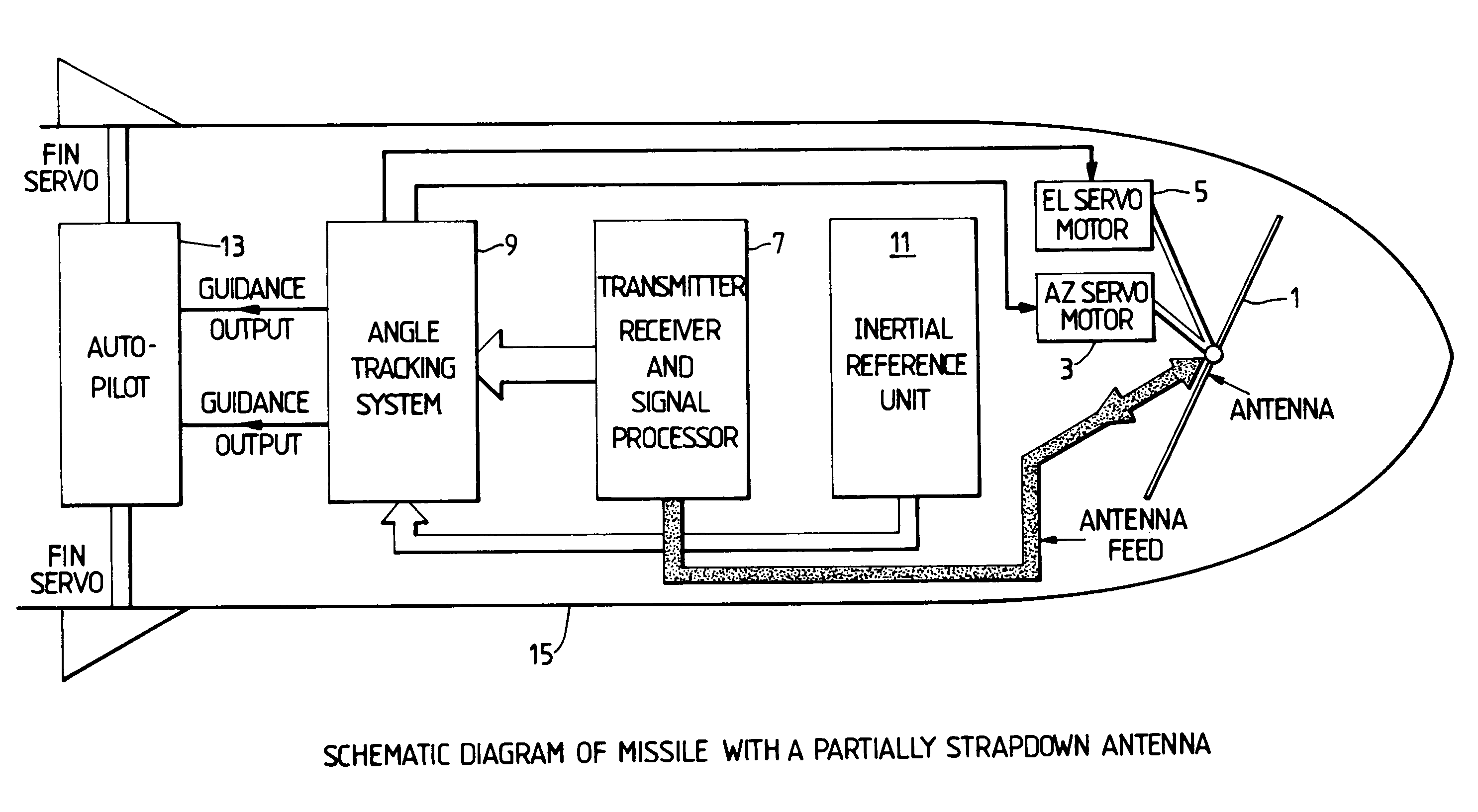
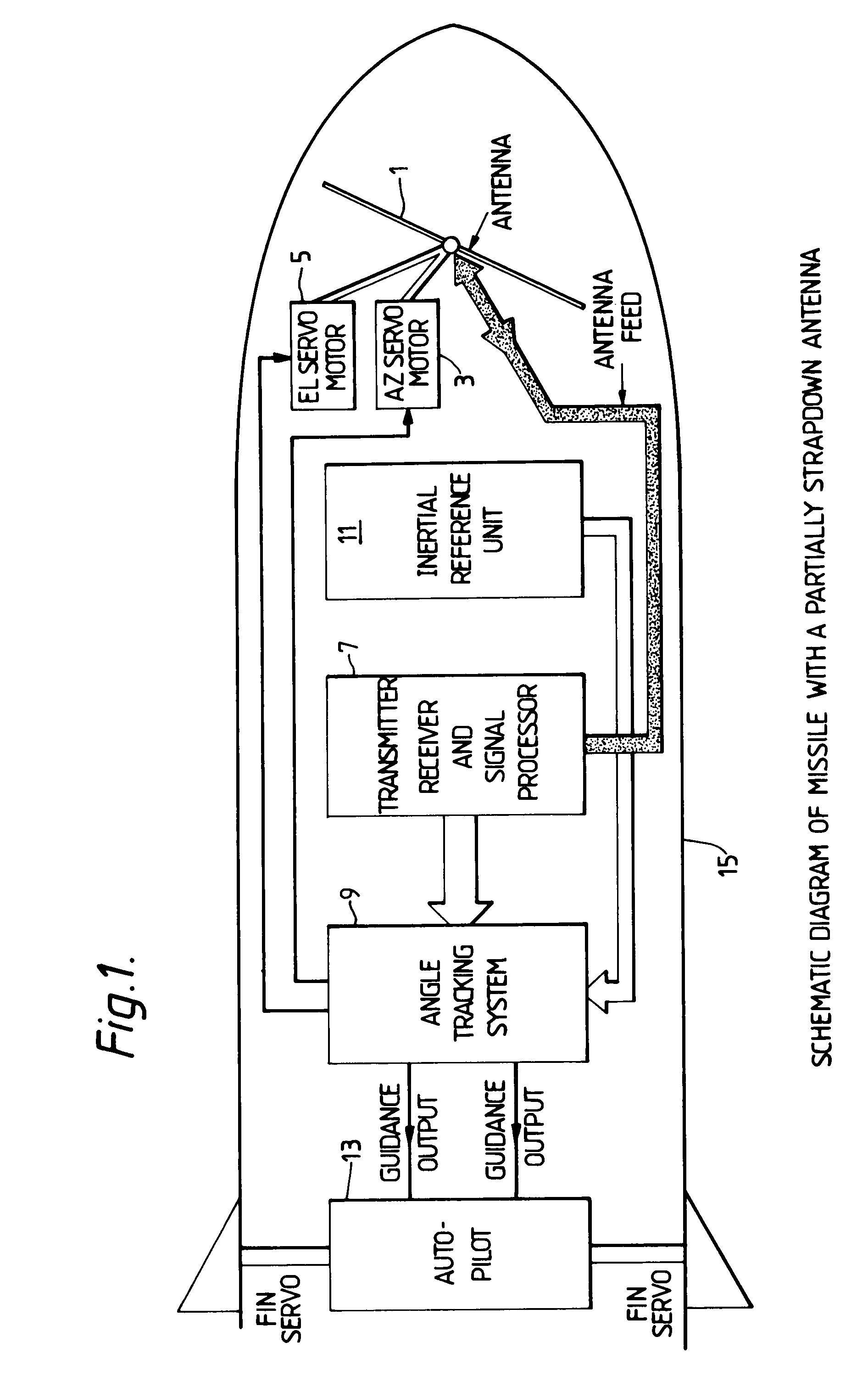
[0016]Referring to the seeker system shown in FIG. 1, the principal elements of the system are:[0017](a) gimballed antenna 1 and associated servo system 3&5;[0018](b) transmitter / receiver 7;[0019](c) electronic angle tracking system 9 including a recursive estimator;[0020](d) strapdown inertial reference unit 11; and[0021](e) guidance unit 13.

[0022]The function of each of these elements is described below.

Gimballed Antenna and Servo System

[0023]The antenna 1 is of a two axis gimballed design. Servo motors 3&5 are driven to cause the antenna to track the target in azimuth and elevation. The outer gimbal is driven relative to the body 15, and the inner relative to the outer gimbal using angle demands obtained from the angle tracking estimator (see later).

[0024]The most important feature of the antenna is that there are no rate gyroscopes mounted on the antenna to measure the angular velocity of the antenna. The mass and inertia of the gimbal mechanism is thus low and therefore the ant...


PUM


Abstract

An angle tracking radar system particularly for a missile with a steerable antenna and gyros strapped down to the missile body—a ‘partially strapdown’ system. The body rate signals, body acceleration signals where provided, and target position signals are converted into an electronic reference frame which is controlled to align with the target sightline, the above body and target signals being employed to produce estimates of target direction, sightline rate and sightline acceleration for use in controlling the missile.

Description

BACKGROUND OF THE INVENTION [0001]This invention relates to tracking systems for radar guided homing missiles. While it is applicable to systems having fixed antennas with electronic beam steering, it is primarily intended for partially strapdown systems, i.e., systems in which a gimbal mounted antenna is stabilised in space by means of gyroscopes strapped down, i.e., fixed, to the body of the missile, as compared to the more conventional gimbal systems where gyros are mounted directly on the antenna.SUMMARY OF THE INVENTION[0002]The object of the present invention is the improvement in the estimation of target direction, i.e., sightline, and sightline angular velocity, i.e., ‘rate’, for an angle tracking system using other than a directly space stabilized antenna.[0003]The addition of stabilizing gyros to a gimbal mounted antenna increases the antenna inertia considerably and so worsens the response, particularly in the presence of highly manoeuvrable targets.[0004]According to the...

Claims


Application Information

Patent Timeline
IPC IPC(8): G01S13/72
CPCF41G7/2213F41G7/2246F41G7/2286H01Q3/08G01S13/883H01Q1/281G01S13/685
Inventor MACBEAN, PETER JAMES
Owner MBDA UK
Learn More