
Fuel cell system having a burner with a flame detection rod therein

a fuel cell and flame detection technology, applied in primary cells, chemistry apparatus and processes, electrochemical generators, etc., can solve the problems of increasing the cost, deteriorating the durability, and deteriorating so as to improve the durability, the response to the flame is deteriorating, and the cost increases.

Inactive Publication Date: 2008-09-02
JX NIPPON OIL & ENERGY CORP
View PDF18 Cites 0 Cited by
  • Summary
  • Abstract
  • Description
  • Claims
  • Application Information

AI Technical Summary

Benefits of technology

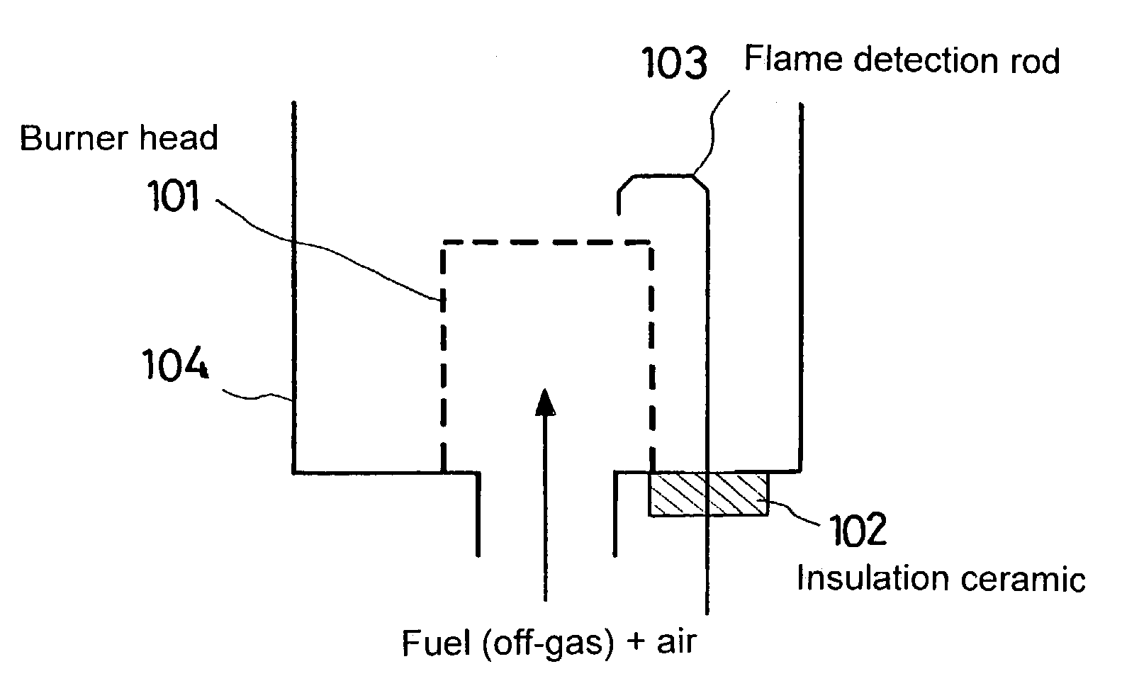
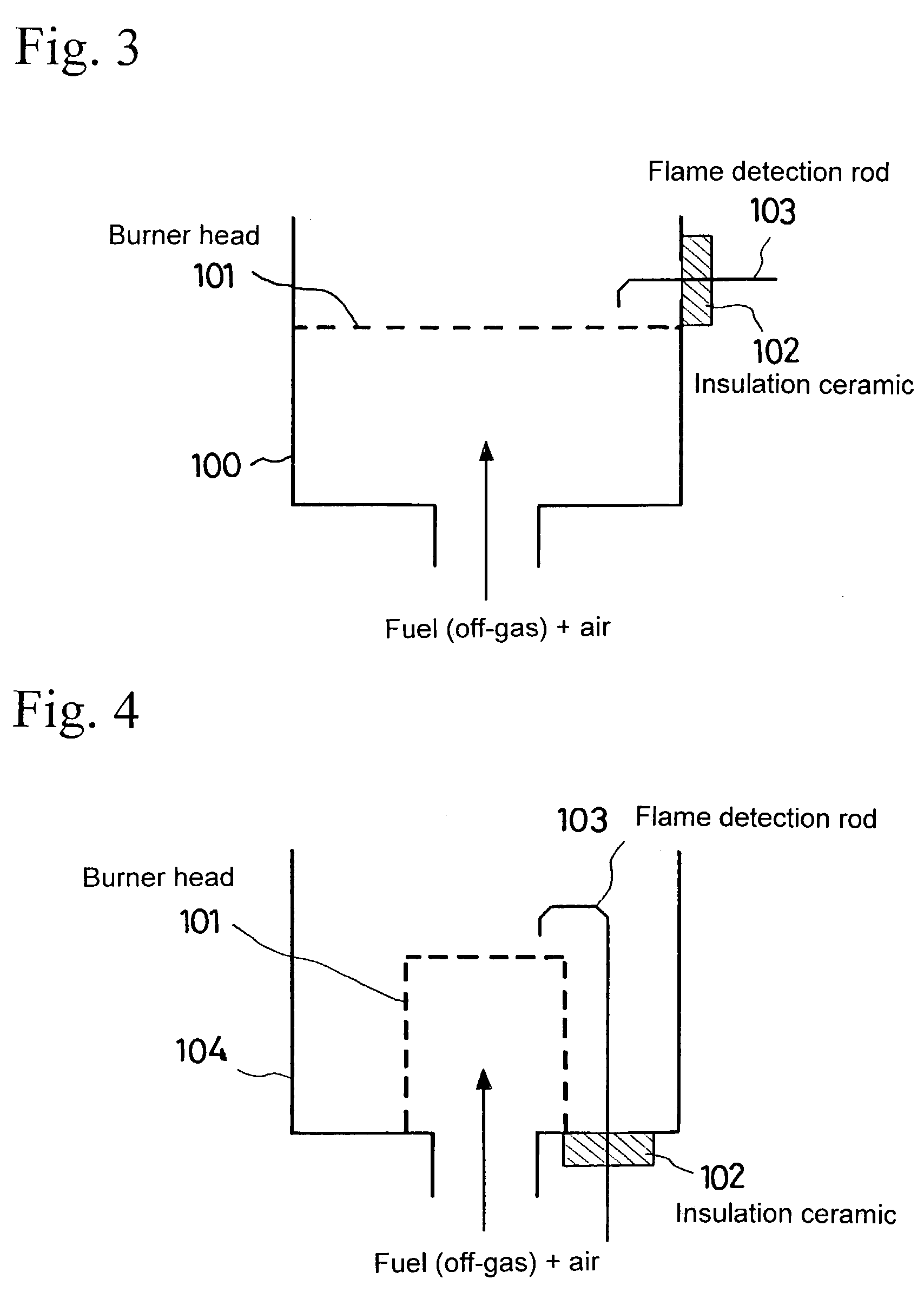
"The present invention provides a fuel cell system with a flame detection system for the burner and process gas burner. The system uses a flame rod system flame detection means and a thermocouple for flame detection. The system does not require additional raw fuel and simplifies the system while ensuring high efficiency. The flame detection system allows for monitoring and control of stable combustion and detection of flame off in the burner. The fuel cell system uses a precious metal base reforming catalyst composed at least of Ru and / or Rh and the fuel gas concentration in the outlet gas of the reformer is controlled to optimize the performance of the system."

Problems solved by technology

In the flame off detection by the thermocouple, the flame temperature is measured directly and the flame off is judged from its temperature change, requiring a detection time (judgment time) of several seconds from the flame off, deteriorating the response to the flame off and, moreover, increasing the cost and, on the other hand, in case of sheath type thermocouple, larger is the diameter of the sheath, lower is the response to the temperature change, imposing to use a thermocouple of small diameter; however, the sheath protection material is eroded and, especially, a sheath type thermocouple of 0.5 mm in diameter breaks when exposed to an open flame, deteriorating the durability.
However, as the flame rectifying effect is generated by ionization of hydrocarbon in the fuel, and a sufficient current does not flow in case of lack of hydrocarbon in the fuel or in case of low concentration of hydrocarbon in the fuel, inhibiting the use of the method in these cases.
Additional supply of raw fuel from the pipe 13 decreases the efficiency, and complicates the system.

Method used


Image

  • Fuel cell system having a burner with a flame detection rod therein
  • Fuel cell system having a burner with a flame detection rod therein
  • Fuel cell system having a burner with a flame detection rod therein

Examples


embodiments

[0091]Now, the present invention shall be described more in detail in reference to embodiments and comparative examples, but the present invention shall not be limited to these embodiments.

embodiments 1 to 3

[0092]Table 4 shows together results of operation of the fuel cell system GS of the present invention, supplying only unreacted hydrogen gas, without supplying additional raw fuel to the burner for reformer 12 provided with a flame rod system flame detection means, under the conditions shown in Table 4.


PUM

PropertyMeasurementUnit
temperatureaaaaaaaaaa

Abstract

The object is to provide a simplified but highly efficient fuel cell system, permitting to perform the flame off detection and so on without supplying the burner with additional raw fuel, even if a flame rod system flame detection means is adopted as burner for reformer. The invention concerns a fuel cell system, comprising a reformer for reforming a hydrocarbon base fuel such as natural gas into hydrogen, a CO transformer, a CO eliminator, a fuel cell for generating electricity from hydrogen, and a burner for reformer for burning hydrogen gas discharged from the fuel cell and supply the reformer with heat necessary for reforming reaction, wherein the burner for reformer is provided with a flame rod system flame detection means and, at the same time, supplied with hydrogen gas containing a flame detectable amount of fuel gas.

Description

BACKGROUND OF THE INVENTION[0001]1. Field of the Invention[0002]The present invention concerns a fuel cell system.[0003]2. Detailed Description of the Prior Art[0004]Of latest years, a fuel cell system, comprising a reformer for reforming a hydrocarbon base fuel including natural gas, city gas, methanol, LPG, butane and so on as raw fuel into hydrogen, a CO transformer for transforming carbon monoxide, a CO eliminator for removing carbon monoxide, a fuel cell for generating electricity from hydrogen, and a burner for reformer for burning hydrogen gas discharged from the fuel cell and supply the reformer with heat necessary for reforming reaction, or a fuel cell system as small power supply comprising further a process gas burner burning hydrogen until each reactor stabilizes during the start or stop, have been proposed.[0005]FIG. 5 is a system diagram showing a fuel cell system of the prior art.[0006]A fuel cell system GS using a fuel cell 6 comprises a heat recovery unit RD in addi...

Claims


Application Information

Patent Timeline
Patent Type & Authority Patents(United States)
IPC IPC(8): H01M8/06H01M8/04C01B3/38
CPCH01M8/04022H01M8/0668H01M8/0612Y02E60/50
Inventor KADOWAKI, MASATAKAFUJU, AKIRAMIYAKE, YASUOUEDA, MASATOSHIMIYAI, KEIGOAKIYAMA, YUKINORI
Owner JX NIPPON OIL & ENERGY CORP
Learn More