Interference microscope, and method for operating an interference microscope

a technology of interference microscope and interference microscope, which is applied in the field of interference microscope and a method for operating an interference microscope, can solve the problem of not providing a higher-contrast measurement signal of the specimen, and achieve the effect of reducing the stress on the fluorescent specimen

Inactive Publication Date: 2010-06-22
LEICA MICROSYSTEMS CMS GMBH
View PDF21 Cites 11 Cited by
  • Summary
  • Abstract
  • Description
  • Claims
  • Application Information

AI Technical Summary

Benefits of technology

[0009]It is therefore an object of the present invention to provide and an interference microscope, and a method for operating such an interference microscope, with which it is possible to determine the phase position of the interfering light in the specimen region, on the basis of which the interference microscope can be aligned.
[0014]What has been recognized according to the present invention is firstly that it is possible to dispense with the detection of individual specimen regions for determination of the phase position if at least one suitably configured planar area of the specimen support unit is used as a reference specimen. Especially in the detection of fluorescent specimens, this reduces stress on the fluorescent specimen to be detected, since the necessary measurements for detecting the phase position of the interfering light can be performed at the planar area of the specimen support unit. Bleaching of the fluorescent specimen merely for purposes of phase determination can thus be avoided, since the measurement for determining the phase position of the interfering light can be performed in a region of the planar area of the specimen support unit that is sufficiently remote from the specimen that the specimen is excited very little or not at all to fluoresce. A reference measurement at a planar area of the specimen support unit using light of a wavelength that is not suitable for exciting the fluorescent markers would also be conceivable, but it also would not furnish a higher-contrast measurement signal of the specimen, since the specimen generally absorbs only weakly.

Problems solved by technology

A reference measurement at a planar area of the specimen support unit using light of a wavelength that is not suitable for exciting the fluorescent markers would also be conceivable, but it also would not furnish a higher-contrast measurement signal of the specimen, since the specimen generally absorbs only weakly.

Method used


Image

  • Interference microscope, and method for operating an interference microscope
  • Interference microscope, and method for operating an interference microscope
  • Interference microscope, and method for operating an interference microscope

Examples


Embodiment Construction

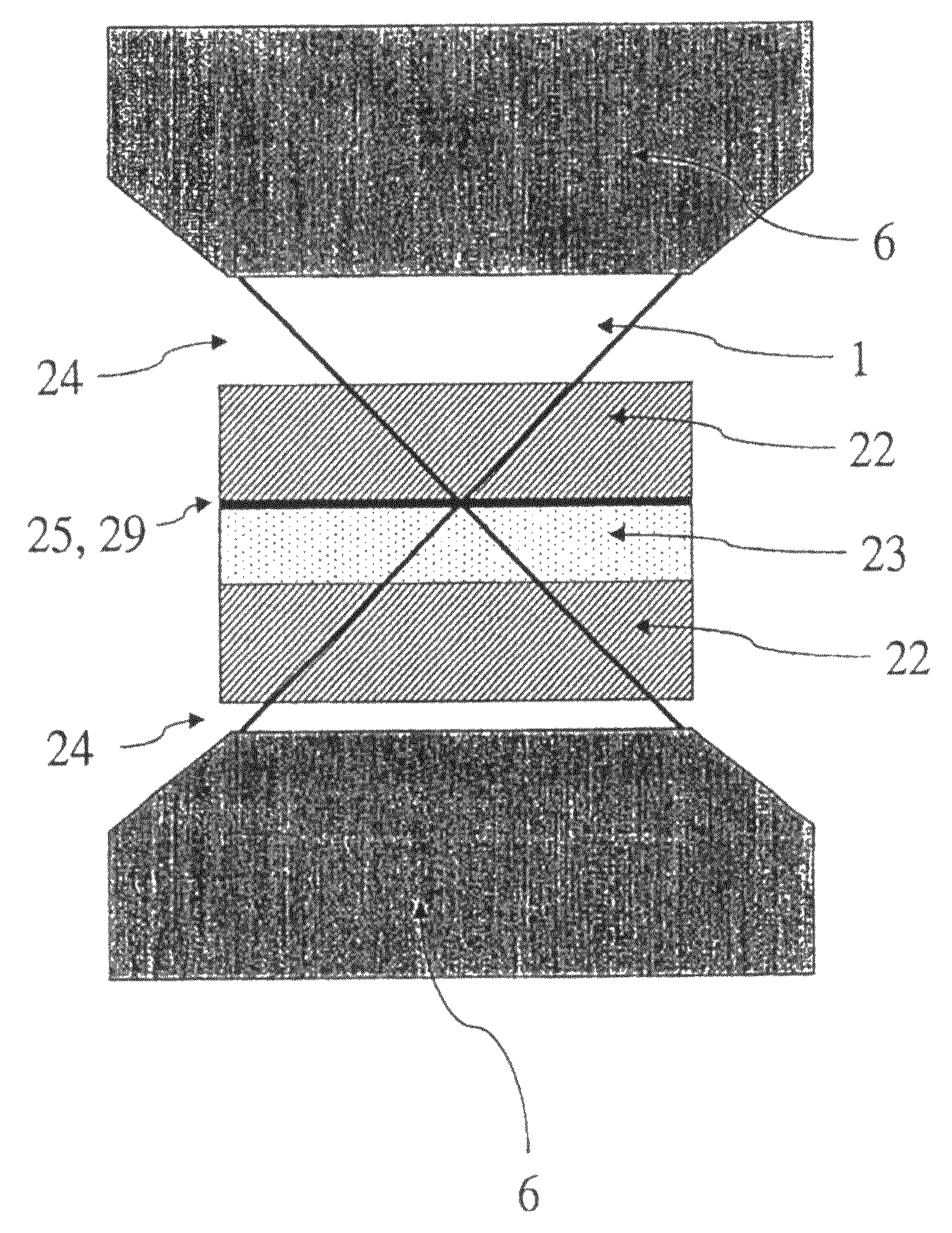
[0031]A planar area of the specimen support unit configured to be detectable by light microscopy could be implemented by way of an at least partially reflective coating of a surface of the specimen support unit, for example in the form of a cover slip coated on one side. As an alternative thereto, the specimen support unit could comprise a reflective or luminescent layer between two glass plates, so that a planar area configured to be detectable by light microscopy is created by said layer. Two glass plates of differing material properties in direct contact with one another could also form a planar area configured to be detectable by light microscopy, for example if the refractive indices of the two glass plates differ, the planar area being detectable by light microscopy by way of the refractive index transition. In addition, the use of crystal or glass plates having holographic coatings or configurations can result in a planar area configured to be detectable by light microscopy. ...


PUM


Abstract

The present invention concerns an interference microscope and a method for operating an interference microscope, in particular a 4π microscope, standing wave field microscope, or I2M, I3M, or I5M microscope, at least one specimen support unit associated with the specimen being provided. For determination of the phase position of the interfering light in the specimen region, on the basis of which the interference microscope can be aligned, the interference microscope is characterized in that for determination of the illumination state in the specimen region of the interference microscope, at least one planar area of the specimen support unit is configured to be detectable by light microscopy.

Description

CROSS REFERENCE TO RELATED APPLICATIONS[0001]This is a divisional of application Ser. No. 10 / 037,538, filed Jan. 4, 2002, now abandoned, which claims priority to German patent application 101 00 247.5, filed Jan. 5, 2001, the entire subject matters of both of which are hereby incorporated by reference herein.FIELD OF THE INVENTION[0002]The present invention concerns an interference microscope and a method for operating an interference microscope. A 4π microscope, standing wave field microscope, or an I2M (Image Interference Microscopy), I3M (Incoherent Interference Illumination Microscopy), or I5M (Image Interference Microscopy and Incoherent Interference Illumination Microscopy combination) microscope is provided, in particular, as the interference microscope. At least one specimen support unit is associated with the specimen.BACKGROUND OF THE INVENTION[0003]Interference microscopes are known from practical use. EP 0 491 289 A1, for example, discloses a double-confocal scanning mic...

Claims


Application Information

Patent Timeline
Patent Type & Authority Patents(United States)
IPC IPC(8): G02B21/06G02B21/00G02B21/34
CPCG02B21/06G02B21/34G02B21/18G02B21/082
Inventor BEWERSDORF, JOERGGUGEL, HILMAR
Owner LEICA MICROSYSTEMS CMS GMBH
Why Eureka
Try Eureka