Hearing aid with antenna for reception and transmission of electromagnetic signals

a technology for electromagnetic signals and antennas, applied in the direction of antennas, antenna supports/mountings, electric vehicles, etc., can solve the problems of affecting the reception and transmission of electromagnetic signals in these frequency bands, and achieve the effect of reducing the space occupied by antennas

Active Publication Date: 2010-06-22
OTICON
View PDF15 Cites 79 Cited by
  • Summary
  • Abstract
  • Description
  • Claims
  • Application Information

AI Technical Summary

Benefits of technology

[0009]By placing the antenna outwardly of the battery the battery may be used as ground, and this is an advantage. Also the position of the battery between the antenna and the other components within the hearing aid will help to ensure, that the antenna does not become de-tuned when the receiver or other components within the shell are fixed at a given position during finishing of custom made hearing aids. Further the battery will provide electromagnetic shielding between the antenna and other parts of the hearing aid circuitry.
[0011]Preferably the antenna is shaped as a part of a flexprint. This construction is advantageous because it is possible to use the flexibility of the flexprint to pride connections across possible moving parts, like from the battery lid to the rest of the hearing aid.
[0012]In an embodiment of the invention the antenna is embedded in material externally of the battery. Embedding the antenna in material will aid to protect the antenna and at the same time minimize the space taken up by the antenna. The embedding may be accomplished by over-molding a flexprint-antenna or a solid metal part. It could also be realized by providing a surface metalization trace on a polymer part of the antenna and then overmolding or covering the surface trace in some other way.

Problems solved by technology

This also means that there is likely to be some noise in these frequency bands, and this is a further reason for the antenna to be effective.

Method used


Image

  • Hearing aid with antenna for reception and transmission of electromagnetic signals
  • Hearing aid with antenna for reception and transmission of electromagnetic signals
  • Hearing aid with antenna for reception and transmission of electromagnetic signals

Examples


Embodiment Construction

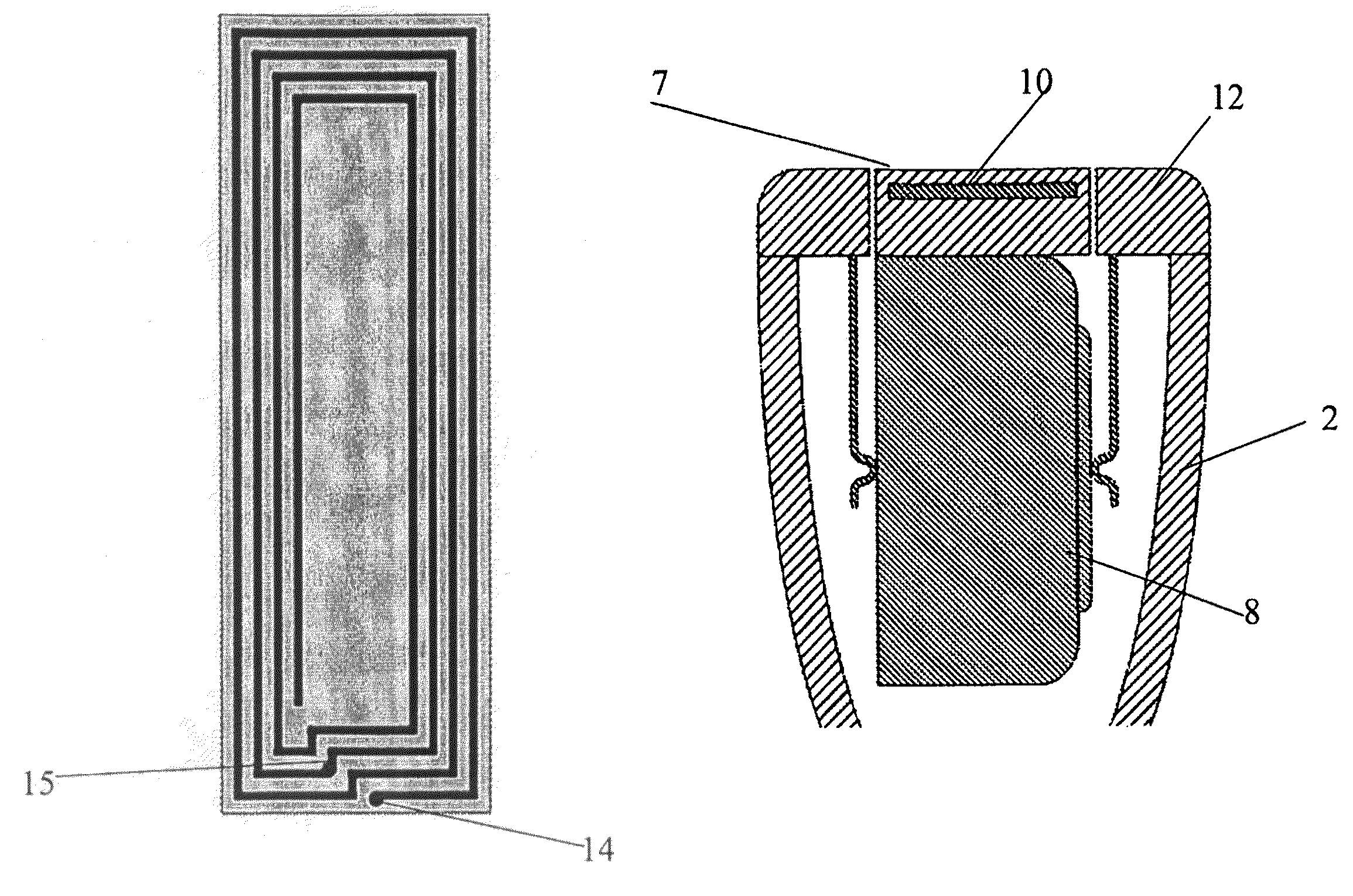
[0021]Initially it is worth noting that we are dealing with small antennas, meaning that the wavelength is much larger than the physical size of the antenna and therefore the antenna has a narrow bandwidth (high quality factors) and low efficiency (small radiation resistance compared to the loss resistance). If high currents are dominating, the structure will mainly radiate the magnetic field and vice versa: if high voltages are present, a dominating electric field must be expected.

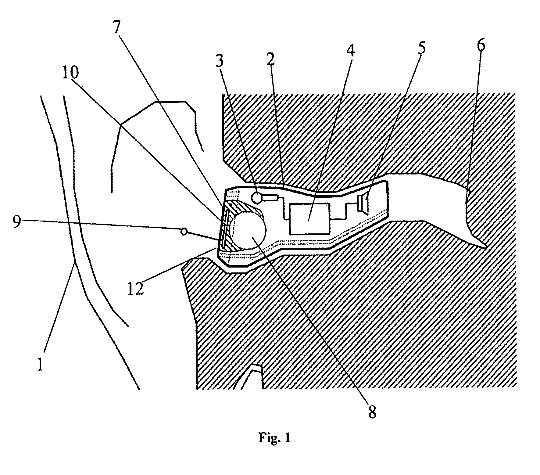
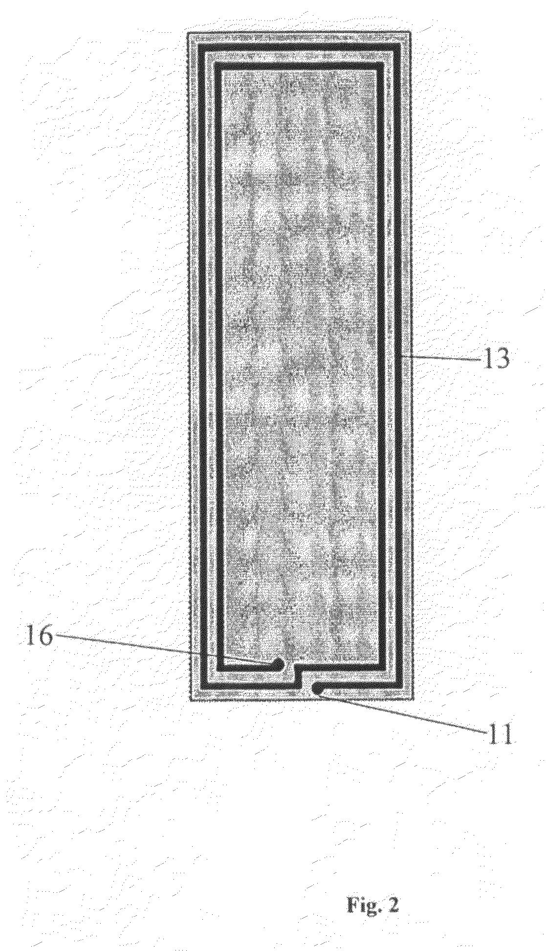
[0022]In FIG. 1 a schematic sectional representation of a CIC hearing aid is shown with an antenna according to the invention. The hearing aid comprises a custom made shell part 2 which is placed deep in the ear canal. Instead of being custom made the shell part can be either flexible or have a flexible outer portion which allows it to be inserted into the ear. 1 is an outline of the external ear of a person. The shell part 2 encloses a receiver 5, a signal processing unit 4 and a microphone 3. The receiv...


PUM


Abstract

The invention regards a communication device which is adapted for placement in a users ear. The communication device comprises a shell part enclosing an input transducer for receiving an input signal, a signal processing device and an output transducer for providing a signal perceivable as sound, a battery located at a surface part of the shell which is facing away from the head of the user, a transmission and reception circuit for transmission and / or reception of electromagnetic energy. According to the invention an antenna for radiating and / or receiving electromagnetic energy is provided such that it has a first surface turned towards the surroundings and a second surface located in close proximity of the battery.

Description

AREA OF THE INVENTION[0001]The invention regards hearing aids or other listening devices wherein-wireless reception and transmission means are provided. Especially in ITE (in the ear) and CIC (completely in the canal) style hearing aids it is a problem to accommodate antennas for the provision of the wireless transmission.BACKGROUND OF THE INVENTION[0002]In small hearing aids which are to be worn in the ear, the distance between the antenna and the receiver or speaker will be small and as a result, the antenna is likely to pick up unwanted electromagnetic radiation. Inside the hearing aid a microphone and a receiver are placed along with a signal processing device and a battery. The receiver delivers a signal to the user which is perceivable as sound but at the same time the receiver will radiate electromagnetic energy and this is likely to be collected by the antenna and may give rise to either feedback problems or noise. Hearing aids of the above kind are often custom made and the...

Claims


Application Information

Patent Timeline
Patent Type & Authority Patents(United States)
IPC IPC(8): H04R25/00H01Q1/12H02J7/00H01Q1/22H01Q1/27H01Q1/44H01Q7/00H01Q9/27
CPCH01Q1/273H01Q1/44H01Q7/00H01Q9/27H04R25/554H04R25/60H04R2225/31H04R2225/49H04R2225/51H04R2420/07H04R2225/025H04R25/609H04R2225/023H01Q1/24H04R25/602H04R2225/33
Inventor CHRISTENSEN, KARE T.KNUDSEN, OVE
Owner OTICON
Why Eureka
Try Eureka