Exhaust gas purification apparatus

a technology of exhaust gas purification and purification chamber, which is applied in the direction of exhaust gas treatment electric control, electrical control, separation process, etc., can solve the problem that the exhaust gas passage cannot be clogged with enough reducing agent, and achieve the effect of preventing erroneous detection of clogging

Active Publication Date: 2010-06-29
VOLVO LASTVAGNAR AB
View PDF47 Cites 20 Cited by
  • Summary
  • Abstract
  • Description
  • Claims
  • Application Information

AI Technical Summary

Benefits of technology

[0008]Therefore, aiming to address such problems, an object of the present invention is to provide an exhaust gas purification apparatus capable of preventing erroneous detection of clogging of an injection nozzle.
[0014]According to the present invention, based on both the pressure of high-pressure air introduced into the reducing agent supply unit which sucks up the reducing agent from the reducing agent tank, and mixes it with high-pressure air for delivery, and the temperature of the injection nozzle that injection-supplies the reducing agent to the exhaust gas moving upstream side of the reducing catalytic converter in the exhaust gas passage, clogging of the injection nozzle is detected by the clogging detection unit, and hence it is possible to prevent erroneous detection of clogging of the injection nozzle.
[0015]Furthermore, according to a preferred embodiment of the present invention, the pressure of the high-pressure air introduced to the reducing agent supply device is compared with the predetermined threshold value by the first comparator, the temperature of the injection nozzle is compared with the predetermined threshold value by the second comparator, the logical AND of the outputs from the first and second comparators is performed by the logic circuit clogging of the injection nozzle is determined by the determination section based on the outputs from the logic circuit when the pressure of the high-pressure air and the temperature of the injection nozzle both exceed each threshold values, and a signal indicating the occurrence of clogging is outputted, and hence it is possible to determine clogging of the injection nozzle easily.
[0016]Moreover, according to a further embodiment of the present invention, high-pressure air whose flow rate is adjusted to be constant, is introduced into the reducing agent supply device, and hence it is possible to detect clogging of the injection nozzle by a change in the pressure of the high-pressure air introduced into the reducing agent supply unit.
[0017]According to a still further embodiment of the present invention, the threshold value of the second comparator is set greater than or equal to the fusing point of the reducing agent, and hence combined with the output from the first comparator it is possible to detect major clogging of the injection nozzle in which deposited reducing agent does not melt in spite of the temperature of the injection nozzle being greater than the fusing point of the reducing agent, or clogging of the injection nozzle due to a foreign substance. Accordingly, minute clogging in which deposited reducing agent melts easily and disappears in the case where the temperature of the injection nozzle increases above the fusing point of the reducing agent, is excluded from the determination of clogging of the injection nozzle, so that it is possible to detect selectively only major dogging that adversely affects the injection-supply of the reducing agent

Problems solved by technology

In this type of exhaust gas purification apparatus, there are situations in which the reducing agent, urea for example, is deposited during injection, and clogging the injection nozzle, so that sufficient reducing agent cannot be injection-supplied to the exhaust gas passage.
However, in the case where clogging of the injection nozzle is determined by detecting the pressure change in the high-pressure air, there is concern that the above-mentioned incorporation of the pressure detecting system may also be sensitive to detecting pressure changes in the high-pressure air produced by minute clogging, which is not a major cause of damage to the injection-supply of reducing agent, for example clogging in which deposited reducing agent will be melted easily by an increase in temperature in the injection nozzle and disappear, so that the system erroneously detects this as clogging of the injection nozzle.

Method used


Image

  • Exhaust gas purification apparatus
  • Exhaust gas purification apparatus
  • Exhaust gas purification apparatus

Examples


Embodiment Construction

[0021]Hereunder is a detailed description of a preferred embodiment of the present invention, based on the accompanying drawings.

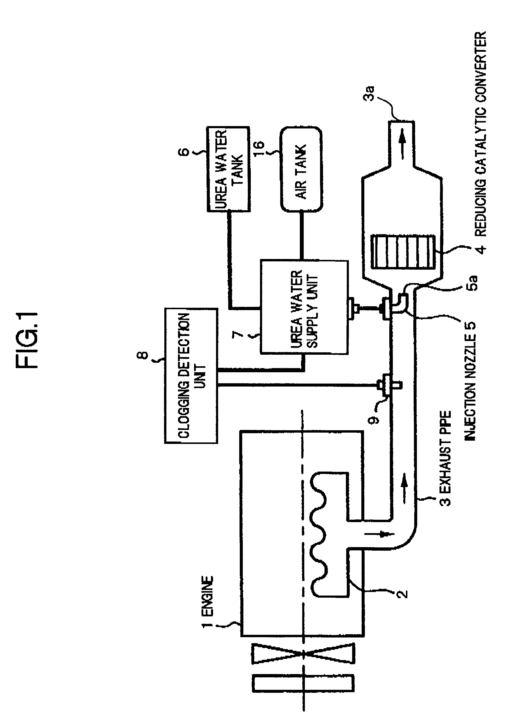
[0022]Referring to FIG. 1, which is a conceptual and diagrammatic view of an exhaust gas purification apparatus according to a preferred embodiment of the present invention, the exhaust gas purification apparatus is provided for reducing and removing NOx exhausted from a diesel engine, a gasoline engine, or the like installed in a moving vehicle, using a reducing agent. The exhaust gas purification apparatus is provided with a NOx reducing catalytic converter 4 and an injection nozzle 5 in an exhaust pipe 3, being an exhaust gas passage which exhausts exhaust gas from an engine 1 whose fuel is gasoline or light oil to the atmosphere through an exhaust manifold 2, is provided with a urea water tank 6 connected to the injection nozzle 5 via a urea water supply device 7, and is provided with a clogging detection device 8 which is connected to the injection no...


PUM

PropertyMeasurementUnit
temperatureaaaaaaaaaa
pressureaaaaaaaaaa
temperatureaaaaaaaaaa

Abstract

An exhaust gas purification apparatus of an engine, capable of preventing erroneous detection of an injection nozzle clogging, and having a reducing catalytic converter disposed in an exhaust system, for reducing and purifying nitrogen oxide in the exhaust gas using urea water; a urea water tank storing the urea water; a urea water supply unit sucking up the urea water from the urea water tank and mixes it with high-pressure air for delivery; and an injection nozzle injecting the urea water mixed with the high-pressure air, into an exhaust gas moving upstream side of the reducing catalytic converter in an exhaust gas passage, and further having a clogging detection unit capable of detecting clogging of the injection nozzle based on each detection output of a pressure of the air introduced into the urea water supply unit, and a temperature of the injection nozzle.

Description

[0001]This application is a continuation of PCT / JP2005 / 019610, filed on Oct. 25, 2005.BACKGROUND OF THE INVENTION[0002]1. Field of the Invention[0003]The present invention generally relates to an engine exhaust gas purification apparatus that reduces and removes nitrogen oxide (NOx) exhausted from a diesel engine, gasoline engine or the like installed in a moving vehicle, by injecting a reducing agent, which is mixed with high-pressure air, into the exhaust gas upstream side of a reducing catalytic converter through an injection nozzle. In particular, it relates to an exhaust gas purification apparatus that prevents erroneous detection of clogging by detecting clogging of the injection nozzle based on the pressure of the high-pressure air and the temperature of the injection nozzle.[0004]2. Description of the Related Art[0005]Several exhaust gas purification apparatuses have been proposed as system for removing harmful matter, especially NOx, from exhaust gas discharged from an engi...

Claims


Application Information

Patent Timeline
Patent Type & Authority Patents(United States)
IPC IPC(8): F01N3/00B01D53/90B01D53/94F02D45/00F01N3/08F01N3/18F01N3/20F01N3/28F01N3/30F01N11/00
CPCB01D53/90F01N3/2066F01N11/00B01D53/9454Y02T10/24B01D2251/2067B01D2259/12F01N2550/05F01N2560/06F01N2560/08F01N2610/02F01N2610/08F01N2900/1811F01N2900/1824Y02T10/47Y02T10/22Y02T10/12Y02T10/40
Inventor NISHINA, MITSUHIROMATSUNAGA, HIDEKI
Owner VOLVO LASTVAGNAR AB
Why Eureka
Try Eureka